
Bolometers have the ability to detect and measure the power of incident electromagnetic radiation. This allows them to be used in a range of technologies, from night vision cameras to far-reaching astronomy projects. Designing bolometers often requires devoting a lot of time and energy to the development phase, as these devices must be optimized for sensitivity and customized for their specific applications. To efficiently design bolometers with increased sensitivity, AltaSim Technologies utilized the simulation capabilities of COMSOL Multiphysics.
A Brief Introduction to Bolometers
The bolometer was first invented in 1878 by Samuel P. Langley, an American astronomer, with the intended use of studying solar irradiance and solar radiation intensity at different wavelengths. Bolometers consist of a strip of conducting material (a conducting absorber) that is thermally insulated from the rest of the device and mounted on a dielectric material, which acts as a heat sink and electrical insulator.
When a bolometer is exposed to incident electromagnetic radiation, the conducting absorber’s temperature increases in comparison to the rest of the device. As this temperature change occurs, the absorber’s electrical conductivity lowers, altering the flow of the bias current. This change in voltage is detected by a voltmeter and because the change is related to the amount of incident electromagnetic radiation, the device can be used as a sensor.
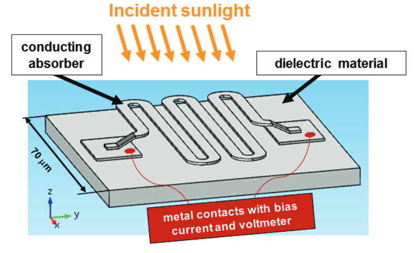
A schematic of a bolometer geometry that shows how the device operates. Image by J. Thomas, J.S. Crompton, and K.C. Koppenhoefer and taken from theirCOMSOL Conference paper submission.
The Many Applications of Bolometers
In recent years, the use of bolometers has extended to night vision cameras and astronomy as well as particle and nuclear physics. NASA, for instance, usestransition-edge sensor (TES) bolometersto sense minor changes that occur in temperature when photons are absorbed and converted into heat. These devices help generate detailed maps for astrophysics projects that illustrate the polarization of cosmic microwave backgrounds.
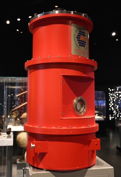
A bolometer array. Image by Geni. Licensed underCC BY-SA 4.0, viaWikimedia Commons.
Researchers at the Herschel Space Observatory are also utilizing bolometers. Their application relates to investigating distant galaxies and the beginning stages of star formation. Doing so involves using a device called theSpectral and Photometric Imaging Receiver (SPIRE), which consists of five arrays of bolometers. Bolometers are ideal in this case because they have the highest sensitivity for light in the far-infrared to millimeter range of any direct detector.
With their range of applications, bolometer designs need to be customized for different uses, while optimizing their overall sensitivity (a key design parameter). When it comes to measuring the design quality, it is favorable that bolometers are able to detect temperature changes of less than 0.0001°C.
AltaSim Technologies recognizes the importance of improving bolometer designs. With the help of COMSOL Multiphysics, they studied the impact of different design parameters on a bolometer’s sensitivity and the level of detection of incident electromagnetic radiation. Let’s see what they found…
Multiphysics Modeling Aids in the Optimization of Bolometer Designs
For their studies, the researchers noted that bolometer functionality is tied to three main physical phenomena:
- Heat transfer within the solid parts of the device
- Conservation of electric currents
- Radiation through the ambient environment
In order to analyze such phenomena, the team used multiphysics modeling to bidirectionally couple heat transfer with electric currents, solving the two elements simultaneously. Solving this coupled electrical and thermal problem involved using a segregated solver approach, using an iterative linear system solver for the current substep and a direct solver for the thermal substep.
As for radiation, testing realistic sunlight conditions was possible via a solar source position functionality available in the Heat Transfer Module. The researchers further applied a uniform normal heating term of 100 W/m2as a smoothed ramp function that ramps from 0 to 100 W/m2over 0.1 s. This is illustrated in the plot below. The model featured a fixed operating temperature of 25 K at the bottom boundary, with a convective heat flux applied to all other boundaries in order to simulate the small cooling effect caused by cooled air inside the bolometer.
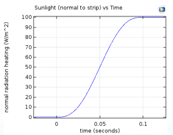
A plot showing radiation heating as a function of time. Image by J. Thomas, J.S. Crompton, and K.C. Koppenhoefer and taken from theirCOMSOL Conference presentation.
Analyzing Bolometer Sensitivity
Now, let’s turn our attention to the sensitivity study. While there are multiple factors affecting the sensitivity of a bolometer — strip spacing, strip aspect ratio, materials, and operating temperatures — the focus here was evaluating the impact of specific design parameters.
In their study, the researchers chose to model a copper material absorbing strip with temperature-dependent material properties. Why copper? As an absorbent material with a strong dependence of conductivity to temperature, copper enabled the team to achieve the greatest sensitivity in their chosen temperature range, 10-50 K (cryogenic temperatures).
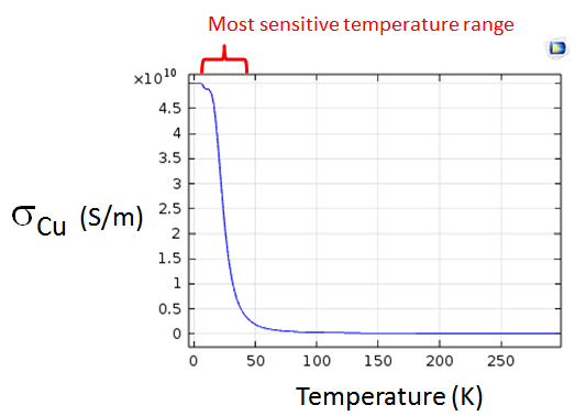
Graph showing the electrical conductivity as a function of T. Here, we can see the most sensitive temperature range for a copper material. Image by J. Thomas, J.S. Crompton, and K.C. Koppenhoefer and taken from theirCOMSOL Conference paper submission.
One point of interest was the dimensions of the contact strip. For this analysis, the team utilized the loft feature in the Design Module for automatic parameterization of the strip spacing parameter. They also generated a free tetrahedral mesh using the default physics-controlled mesh in COMSOL Multiphysics.
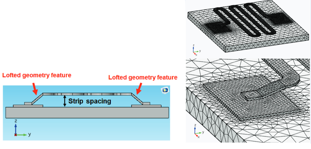
Left: Parameterization of the strip spacing. Right: Tetrahedral mesh. Images by J. Thomas, J.S. Crompton, and K.C. Koppenhoefer and taken from theirCOMSOL Conference paper submission.
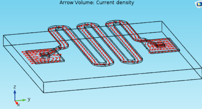
The simulation analyses generated results for the temperature, current flow, and voltage caused by incident radiation at 0.2 s. Sensitivity, represented bySin this study, was defined as the change in voltage divided by the amount of absorbed incident light wattage.
Temperature (left), current flow (middle), and change in voltage caused by incident radiation (right) at 0.2 s. Images by J. Thomas, J.S. Crompton, and K.C. Koppenhoefer and taken from theirCOMSOL Conference paper submission.
To judge how strip spacing affects sensitivity, the researchers performed a parametric sweep for different strip spacing values. In order to account for the voltage drop change for the different configurations of the serpentine length, the sensitivity was normalized by an initial voltage drop. As the graph below indicates, increasing the space between the mounting board and serpentine absorber led to improved bolometer sensitivity. These results provided valuable information to the team at AltaSim, allowing them to move forward in creating a sensitive bolometer design that can more accurately detect and measure the power of incident electromagnetic radiation.
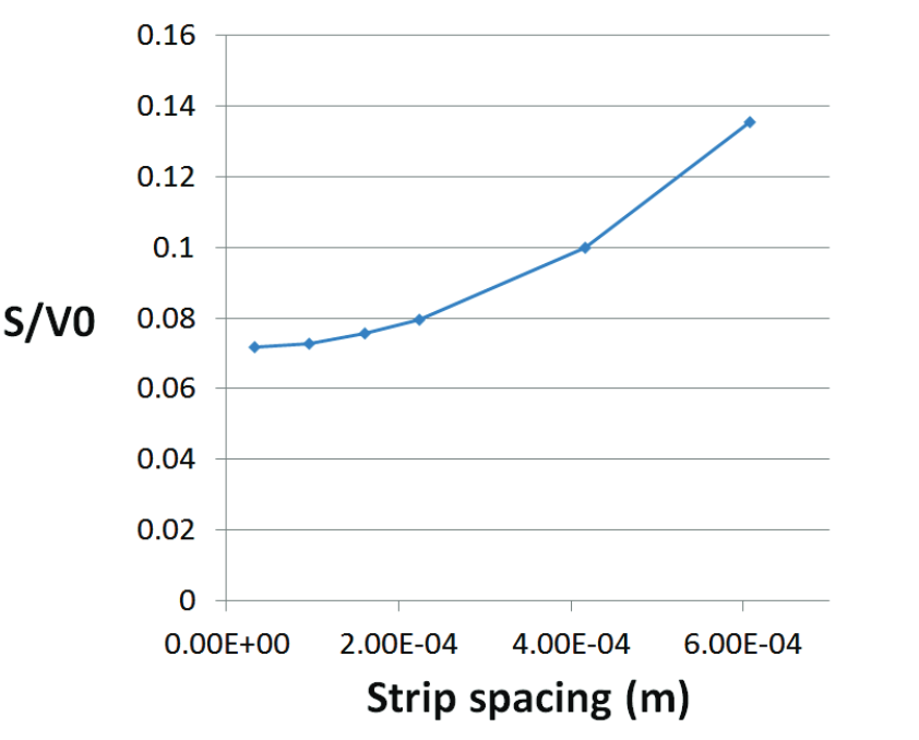
A graph highlighting the effects of strip spacing on bolometer sensitivity. Image by J. Thomas, J.S. Crompton, and K.C. Koppenhoefer and taken from theirCOMSOL Conference paper submission.
Simulation Helps to Advance Bolometer Research and Design
The simulation study presented here can be used to create customized bolometer designs for specific applications and identify other methods for maximizing device sensitivity. For the research team at AltaSim, the computational model can further serve as a foundation for examining additional design parameters that affect the sensitivity of the device. For example, they could study materials that are specially designed to be sensitive to conductivity at room temperatures. Further points of focus in the team’s simulation research include analyzing the serpentine geometry, strip material selection, and bias current magnitude.
Learn More About AltaSim’s Uses of Multiphysics Simulation
- Take a look at the full paper: “Multiphysics Analysis of an Infrared Bolometer“
- Read this blog postto learn about how AltaSim is designing and deploying simulation apps for a variety of uses




Comments (2)
Majid Aalizadeh
November 29, 2018I’m going to simulate a Bolometer with COMSOL but I can’t do it because I don’t know which physics is needed. If you can help me or if you could to send me a simulation file I’ll be very thankful. Thanks
Brianne Costa
November 29, 2018 COMSOL EmployeeHello Majid,
Thank you for your comment.
For questions related to your modeling, please contact our Support team.
Online Support Center:https://www.comsol.com/support
Email:support@comsol.com