We’ve all encountered hinges before; they are frequently used to connect different parts of mechanical assemblies in a way that allows them to move freely relative to one another, in a single degree of freedom. There are several different types of hinges, including everything from barrel hinges to friction hinges, with lots in between. Before incorporating a hinge into a mechanical assembly, you might want to get a sense of how it will hold up by performing a hinge analysis.
Modeling an Assembly with a Barrel Hinge
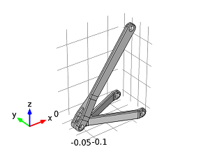
Let’s suppose we need to analyze an assembly that uses a barrel hinge. Two solid objects in the assembly are connected via the barrel hinge, which then allows relative rotation solely along the axis of the pin hole. All other degrees of freedom are common between the two parts at the center of the pin hole. The forked bottom section contains two holes that are bolted and can be considered fully constrained. In order for the top part to slide in the y-z plane, its pin hole is constrained in the x-direction.

Geometry of a barrel hinge.
Now consider that a force of 1 kN is applied in the z-direction at a distance of 10 cm from the upper pin hole’s center in the negative y-direction. This force will introduce both tension and bending in our barrel hinge structure. In order to understand more about how the barrel hinge will be affected, we can set up a model in the Structural Mechanics Module to perform our hinge analysis.
Results of the Hinge Analysis
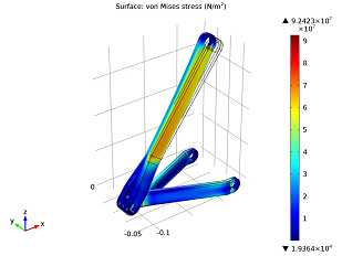
When we plot the von Mises stress distribution we can see that the top part of the hinge experiences bending. That is because of the offset of the load. The plot also illustrates that stress is transmitted around the hinge.
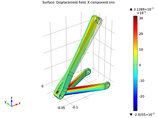
If we then create a second surface plot we can analyze the x-displacement of the hinge. Doing so tells us that there is also bending in the lower part of the assembly.
 |
 |
| The hinge assembly’s von Mises stress distribution. | The x-displacement in the barrel hinge. |
Note that when modeling mechanisms, i.e. rigid bodies connected with joints, in general you’ll want to use theRigid Connectorfeature in the Structural Mechanics Module to attach rigid connectors to both parts. You then want to ensure the connectors have a common center of rotation, and couple relevant degrees of freedom between them.
When creating a hinge model specifically, all translations and two rotations need to be equal in both parts of the assembly. In the case shown here, the hinge displacement and rotation remain small, meaning we just had to link the displacement in all directions, as well as the rotation around the x- and z-directions. TheRigid Connectorfeature recommended the displacement setting needed for directly connecting the displacements of the rigid connectors. If we were to constrain the rotation directions independently, we would have needed to add two global constraints (one for each rotational degree of freedom). TheRigid Connectoruses a representation of the rotation that avoids “gimbal lock” by using quaternions.
Further Reading
Learn more about theAssembly with a Hingemodel in the Model Gallery. Try setting it up on your own by following along the model documentation!
In addition to hinges, bearings are a common way of connecting assemblies to allow two parts to move freely in relation to each other. If you enjoyed this blog post, you might also like to read aboutmagnetic bearings.


Comments (0)