
Our newest release, COMSOL Multiphysics version 4.3b, contains so many new modules and features, certain additions might get lost in the fray. One addition to the COMSOL Multiphysics base package we don’t want you to miss is the ability to create 2D models from cross sections of 3D geometries. This easy-to-use feature allows engineers to simplify the model, gain understanding of and fine-tune parameters, and dramatically reduce simulation time.
3D Models Can Be Quite Complex
Often, your geometries are available as 3D CAD model files and are invariably computation-heavy when simulating a variety of coupled physics. This leads to a significant conundrum because changing the model slightly means re-solving, and for computation-heavy models this can be a time-consuming process. Should users have to rely on assumptions about the physics they are simulating just to keep projects within a manageable scope? The computers available are simply not fast enough for some extremely complex simulations. This leaves us with two possible solutions: inventing more powerful computers (if we could, we would), or simplifying the models.
Therefore, we have added a feature for creating 2D models from the cross sections of 3D geometries inCOMSOL Multiphysics 4.3b. This feature is able to simplify the geometry without diminishing its integrity, as seen in the images below. Even with only moderately complex CAD models, this feature can really improve workflow. You can create 2D cross sections from any 3D model, whether that model was created in 2D originally, created in 3D and imported into COMSOL, or synchronized using the LiveLink™ products. We hope that you will take advantage of this valuable new functionality as you develop your simulations.
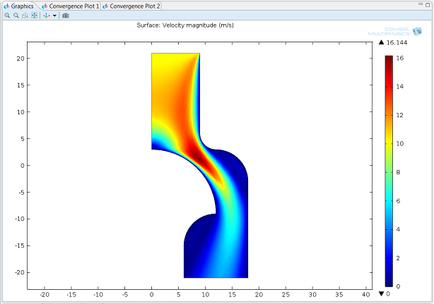
A 2D model was created by taking a 2D work plane from the middle axis to the edge of the 3D geometry, as the original 3D geometry was symmetrical around the axis. The simulation was of Non-Newtonian Flow, and it took 3-4 seconds to solve. If the simulation included other physics, like heat transfer, or required nonlinearities with greater complexity, it would have taken a bit longer to solve.
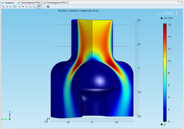
Revolution of the 2D axisymmetric Non-Newtonian Flow model from above using the postprocessing features included in COMSOL Multiphysics.
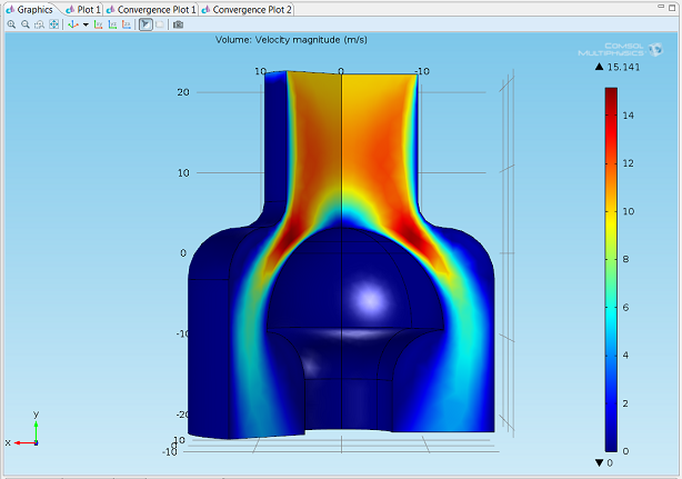
The same model done in 3D produces the same results as the solution presented with the revolved postprocessing of the 2D axisymmetric model. This model took 3-4 minutes to solve. Yet, if the simulation had included other physics, such as heat transfer, or required nonlinearities with greater complexity, it would have taken longer to solve.
Simplify to Understand and Perfect
Creating 2D models from 3D geometries is a simple process. Once you’ve established a suitableWork Planeto intersect with, add a 2D model from the root node, with similar physics and study type as its 3D counterpart. Add aCross Sectionfeature to theGeometrynode of the 2D model.
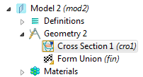
Now, from theWork planedrop-down menu, select theWork Planewith the appropriate cross section node in it.
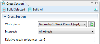
Build the geometry, and now you have a simpler model with comparable solutions. This is the perfect complement to a computation-heavy model with long solution times.
There’s More to Consider
The above example shows a geometry that could be simplified due to its symmetric properties. However, there are many 3D CAD model files where symmetry does not exist, and all the details in 3D need to be considered for an accurate model. How does this feature help in these situations?
In a later blog post, I will show such an example where a geometry cannot be adequately modeled in 2D, but where doing this will still significantly reduce your workflow time. Among other uses, a 2D model can be used to gain understanding of the model concept or to fine-tune parameters, such as solver settings, used in the 3D model. Furthermore, both the 2D and 3D models are created in the same file, facilitating easy workflow between the 2D and 3D views, and allowing you to go back to your 2D model if more fine-tuning is required.
Keep an eye on this blog to see an example of this, with a video demonstrating the process for achieving this great feature for an intricate 3D model, in the coming weeks.


Comments (9)
SaeidS
May 8, 2013Nice addition!
Ivar Kjelberg
May 9, 2013Great !
I have been waiting for this since 3.5
Daniel Höche
May 24, 2013This truely helps and reduces the “conversion” work
Akmal
June 6, 2013surely helpfull!!
Saoni Banerji
July 5, 2016In version 4.3a, we do not have this added functionality of importing the converted 2D workplane as a cross-section for a new model, right? What is the alternative that we could use in that case for 4.3a
Ahmed Iftekhar
September 28, 2016I have a 3D heat transfer and laminar flow model. I want to get the cross line view of the results, i.e the temperature contour. But I want it in 2D.
I tried your process, including the materials and the physics but I have not got anything. Is there any post with more details?
Andrew Griesmer
September 29, 2016 COMSOL EmployeeAhmed – you can try following the instructions in a related video with more detailed instructions:https://www.comsol.com/video/creating-2d-models-cross-sections-3d-geometries
If you are still having issues, please contact your support team at comsol.com/support
Ahmed Iftekhar
October 4, 2016I got that plot. I had 3D model. So, I just use a 2D plot group and surface plot. I introduced a cutline with the measurement of the cross section and I just plot it. It was simple and straightforward.
Rajiv Ghimire
October 4, 2023I tried this. I have a microfluidic channel 3d model which has converged and has given the results. I create a 2d model from the mid plane of the design and do the same study as the 3d model. However the concentration of diluted species (TDS) models did not come out right. What could be the problem?