Today we have the pleasure of welcoming Nagi Elabbasi of Veryst Engineering as a guest blogger. Read on to see what this COMSOL Certified Consultant has to say about fluid-structure interaction.
Two weeks ago I led a webinar on fluid-structure interaction (FSI) using COMSOL Multiphysics. FSI involves coupling between a deformable or moving structure and a surrounding or internal fluid flow. There is a growing number of engineering and scientific problems where a purely structural or purely CFD analysis just aren’t accurate enough. Both analyses have to be accounted for simultaneously. Some examples are valve chatter, damping in MEMS, cardiovascular modeling, and shock absorbers.
Fluid-Structure Interaction Analysis Capabilities in COMSOL Multiphysics
The webinar highlighted the important features and capabilities available forFSI analysis in COMSOL Multiphysics, including the types of FSI coupling, the solution algorithms used, the available solvers, and the handling of the moving fluid mesh. COMSOL provides a wide range of capabilities for the advanced user, and also automates most of the steps required for FSI analysis, which is great for both novice and advanced users.
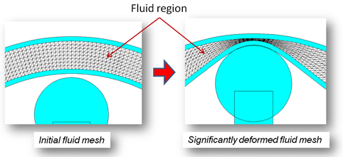
COMSOL offers two types of solvers for fluid-structure interaction problems (as well as other multiphysics problems). The first is the fully coupled solver, ormonolithicsolver as it is sometimes called in literature, and the second is the segregated solver (orpartitionedsolver). Having both solvers enables optimal solver selection for a wide range of FSI problems. The default solver settings work well for most problems, but there are also a lot of solver functionalities for advanced users to adjust for tougher problems. The fluid mesh movement algorithm can also handle severe mesh deformation, as shown below.

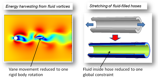
We also demonstrated how we at Veryst Engineering used COMSOL Multiphysics to set up two “non-standard” FSI problems and make engineering simplifications that significantly reduce solution times. In the case of asea floor energy harvester, the solid part of the model was reduced to one degree of freedom (vane rotation), and in the case of the stretching of a fluid-filled hose, the enclosed fluid region was reduced to a single global constraint.

Peristaltic Pump Model
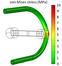
After the two non-standard FSI problems, we showed an interesting FSI example involving a 3D peristaltic pump. Peristaltic pumps move fluid by squeezing on a tube, causing the fluid inside to move. The deformation of the tube is strongly coupled to the fluid flow inside it, so an FSI analysis is required. The model is also nonlinear due to the large rotations of the roller, the nonlinear material response of the tubes, and the contact between the rollers and the tube. We were able to use this model to predict stresses in the tube and flow conditions, including flow fluctuations. The figure below shows the von Mises stresses in one tube configuration. You can find more details on thispump model in a paperwe presented at the COMSOL Conference 2011.

Live FSI Demo using COMSOL Multiphysics
We also held a live demo, showing the important steps involved in setting up and running a fluid-structure interaction analysis in COMSOL. We set up a 2D simplified version of the peristaltic pump model that captures some of the flow characteristics of the full 3D model.
Interested in learning more about FSI analyses? There is anarchived version of the FSI webinaravailable for your viewing.
About the Guest Author
Nagi Elabbasi, PhD, is a Managing Engineer atVeryst Engineering LLC. Nagi’s primary area of expertise is modeling and simulation of multiphysics systems. He has extensive experience in finite element modeling of structural, CFD, heat transfer, and coupled systems, including fluid-structure interaction, conjugate heat transfer, and structural-acoustic coupling. Veryst Engineering provides services in product development, material testing and modeling, and failure analysis, and is a member of theCOMSOL Certified Consultant program.


Comments (15)
NI JUNJUN
September 7, 2013Benefit a lot !
Montassar Aidi Sharif
March 18, 2014Hello I need your Help I Have posted a question 4 days ago but no reply ??
Ian Chuang
October 6, 2016Dear Nagi,
I looked over the example you included in the webinar. A boundary load was set as FEx FEy FEz in the FSI, and you noted that it is the force generated by the electrostatic forces. Does Comsol not directly couple FSI and electrostatic together? Why do you need to set this load?
Ian
Nagi Elabbasi
November 4, 2016Dear Ian, you are right, COMSOL directly provides that electrostatic load. I generated the load myself but it’s easier to use the predefined one in COMSOL. Regards, Nagi
Alexander Werth
November 10, 2016Dear Dr. Elabbasi,
thanks for blogging! Would your model be able to handle contact between walls of the tube resulting in separation of the fluid domain?
Currently I’m working on a 2D model of human glottis using fsi toolbox. I do often observe convergence issues when solid reaches the boundary of the fluid domain resulting in separation of fluid domain. Is automatic re-meshing obligatory for such kind of problems?
Many thanks in advance!
With kind regards
Alexander
P.S.:
My question with further details
https://www.comsol.com/community/forums/general/thread/129601/
Nagi Elabbasi
November 21, 2016Dear Alexander,
I did not use automatic remeshing for this problem, and I prefer not to use it for such cases where a fluid domain nearly collapses. The key is not to let the fluid domain totally collapse. If it gets very narrow that’s good enough and the flow through it should be negligible since pressure drop over flow rate is inversely proportional to the third or fourth power of the opening size, depending on the problem. You can do that by adding an offset to the contact definitions.
Another tip is to make the fluid mesh distort in such a way that the elements stay nearly rectangular as the fluid domain closes. Even though their aspect ratio will be high as the gap closes, they will not “invert”. That cannot be done in all problems, but certainly in this model, and also in models involving heart valves.
Good luck.
Nagi
Alexander Werth
November 24, 2016Dear Nagi,
many thanks for your response. It helps a lot. I switched completelly to quadrangular mapped mesh instead of triangular one in combination with automatic re-meshing. How can I define an offset in order to prevent mesh distortion? I tried to introduce contact pairs of solid domain boundary and fluid domain wall but it did not work. I use the function “Form Union” to set the complete domain (solid and fluid). There is a tutorial on contact modeling with MEMS toolbox but I did not find any information how to model contact when solid and fluid are involved.
Many thanks in advance
Alexander
Alexander Werth
November 24, 2016picture and further details:
https://www.comsol.com/community/forums/general/thread/130761/#p288271
Nagi Elabbasi
November 24, 2016Dear Alexander,
If the two surfaces were parts of solid mechanics domains then contact with offset is straightforward to define in COMSOL. In your case you can add a very stiff solid structure to the wall on the right and then define contact as I described above. Alternatively, you can add a nonlinear spring to the existing solid surface with an initial stiffness of zero that increases when the gap size gets close to zero (or more accurately, when the gap gets close to the smallest gap value that you accept). That is, in essence, how penalty contact works!
I hope this help.
Nagi
Alexander Werth
November 24, 2016Dear Nagi,
it helps a lot! I’m very grateful for your advices.
Alexander
Mohanad A
November 25, 2016Deer Dr. Nagi
My question is not related to the topic above,But I couldn’t find an answer elsewhere. my question is can I simulate Nozzle spray (mist) with COMSOL and find the droplet size?if so, how?
please help
thanks in advance
Nagi Elabbasi
November 27, 2016Dear Mohanad, this is indeed a different topic. I suggest you post your question to the COMSOL Forum and hopefully people will answer. Nevertheless, here is my brief opinion. Spray simulations are doable but the simulations are usually quite demanding. In many engineering problems analytical calculations on sprays/atomization provide sufficient answers. The following COMSOL blog on spray simulation is quite informative:https://www.comsol.com/blogs/cfd-inkjet-model/.
Regards,
Nagi
Chen Peixuan
September 19, 2018Dear Dr. Nagi,
During modelling of FSI, I also have a problem about wall contact. Could you please tell me how to set an offset distance of a moving object to the wall so that the object can not hit the wall?
Thank you in advance,
Best regards,
Peixuan
Sinto Poly
April 24, 2019Dear Dr. Nagi,
Can you please post a tutorial for Fluid-Structure Interaction Analysis of a Peristaltic Pump, step by step?
Sinto poly
Kaleem Iqbal
November 5, 2020Dear Dr. Nagi, How we implement or any application in comsol 5.5 related to FSI with optimization?