When designing a perforated well to recover oil and gas, choosing the right number of perforations with the appropriate properties is key. Too many holes and you run the risk of equipment failure or injury; too few and you decrease productivity levels. One way to achieve this balance and improve the safety and productivity of the recovery operation is to model fluid flow near the wells. Let’s see how the Application Builder makes this process even more efficient.
Preparing Wells to Recover Oil and Gas from Reservoirs
Wedged between layers of porous or fractured rock formations are two of the natural resources that we rely on most: oil and gas. Recovering resources from these areas of accumulation, known as reservoirs, is a key point of focus for the oil and gas industry. For an efficient recovery process, engineers working in this field can design wells that effectively recover the oil and gas that fills the reservoir formations.

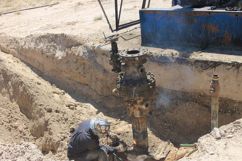
Wells are drilled at specific locations to recover valuable resources. Image by Caitlin Heryford. Licensed underCC BY 2.0, viaFlickr Creative Commons.
One way to establish flow communication between the reservoir and the well is through the use of perforations. After drilling a well and adding a casing to provide further protection and stability, holes can be shot through the casing and cement at specific locations via a perforating gun. This produces a path that allows fluid to flow from the reservoir to the well. Perforated wells are particularly beneficial in the sense that the perforations can be sealed individually, providing greater control over the well itself.

An image showing perforations in steel. Image by Mr Thinktank. Licensed underCC BY 2.0, viaFlickr Creative Commons.
The safety and productivity of a perforated well is greatly impacted by its design, from the number of perforations that are included to their size and orientation. Therefore, to prevent damage to equipment and injuries to personnel, as well as to maximize the production of hydrocarbons, it’s important to first analyze the fluid flow in the well and obtain a better understanding of the fluid intake at each perforation. Numerical modeling apps, as we’ll highlight in the next section, offer an optimized solution for doing just that.
Using an App to Better Predict Fluid Flow Intake in a Perforated Well
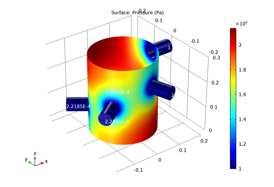
OurPerforated Well demo appis based on a model that simulates Darcy flow within a perforated wellbore (the hole that forms the well). Modeling this process requires performing a full 3D analysis in the COMSOL Multiphysics® software. The plot below shows the pressure at the wellbore and pumping rates for a given set of parameters.

Simulation plot depicting the pressure at the wellbore as well as the pumping rates. Note that annotations of values can be directly included in the plot.
Say a user now wants to compare these initial results with the results from a new set of design parameters. Rather than turning to simulation experts to run further rounds of tests, these users now have the power to run their own analyses with an easy-to-use app. By hiding the complexity of the underlying model behind a simplified interface, apps enable those with little knowledge of simulation processes to achieve accurate simulation results quickly.
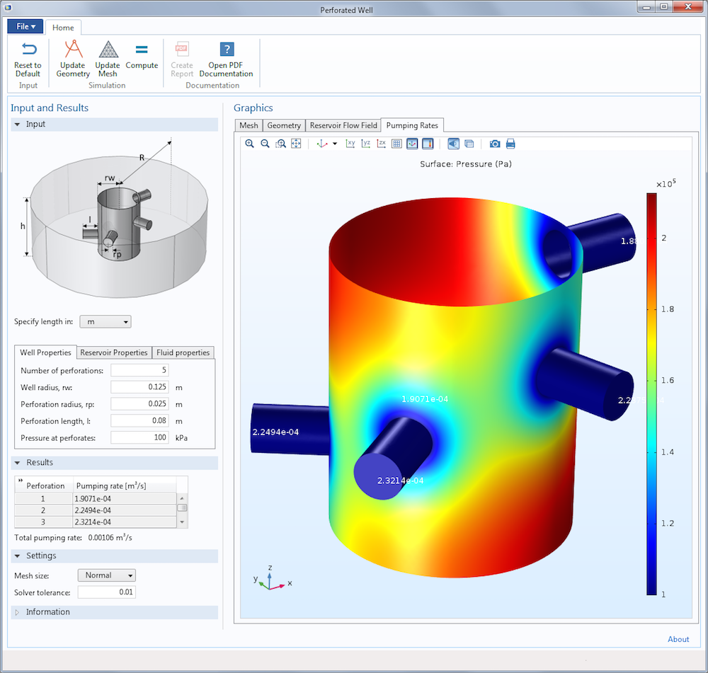
To get a better idea of the functionality that can be included in such an app, let’s go back to our perforated well example. This demo app provides users with the option to modify a number of parameters. With regards to the well, they can specify its radius, the number of perforations, the perforation radius and length, and the pressure at the perforations. Users can also modify the viscosity and density of the fluid as well as the radius, porosity, thickness, permeability, and pressure of the reservoir. Keep in mind that when creating an app of your own, you have control over which parameters users have the ability to change — as well as the structure and organization of the app.

The user interface (UI) of the Perforated Well app.
As highlighted in the screenshot above, the results generated by the app are shown in the Graphics window. In addition to a plot of the pressure at the perforations and the pumping rates (as referenced earlier), the app also plots the flow field and pressure drop in the reservoir. With all of the underlying model’s physics included in the app and controlled parameters, users can be confident in the reliability and usefulness of their simulation results.
Efficiently and Accurately Design Perforated Wells with the Application Builder
Perforated wells offer a viable approach for accessing oil and gas trapped in reservoirs. Ensuring the safety and productivity of these wells is a more streamlined process thanks to simulation apps, which empower a larger group of people to run their own simulation tests. Extending the scope of simulation capabilities paves the way for further advancements in the field of well design, which could potentially help recover oil and gas from even more complex rock formations with smaller permeability.
More Inspiration for Your App-Building Processes
- Get a quick introduction on how to turn your COMSOL Multiphysics model into an app bywatching this video
- Gain inspiration and guidance for building your own apps by browsing blog posts in ourApplications category


Comments (1)
Molika Linkolnli
March 7, 2018Dear Bridget,
Is it possible to use a dual permeability model here?
That is, fluid flow for both matrix and fracture, they have defined two separate equations and connected to each other with a transfer function and shape factor as a fracture matrix interaction.
If yes, which modules should be reset?
Please advise.