
We have the pleasure of introducing a new guest blogger, Mark Yeoman of Continuum Blue, who showcases what they can do for their biomedical engineering clients.
In a recent webinar, I had the opportunity to highlight some of the great things we at Continuum Blue are doing in the biomedical field. In this guest post, I will delve deeper into how we use COMSOL software to help clients improve bioreactor performance and show you a bioreactor modeling example.
Why COMSOL?
More and more biomedical researchers and engineers are turning to multiphysics simulations to find solutions to their problems. With COMSOL Multiphysics, these simulations are made easy; the software helps us to simplify the analysis of difficult biomedical processes. Thereby, it is easier forour clientsto understand biomedical processes, improve products, and test product performance before prototyping and production.
A Bioreactor Modeling Example
In awebinar on multiphysics simulation of biomedical engineering applications, I presented three models. One was used for assessing the bone remodeling of a patient’s femur, i.e. leg bone, following total hip replacement (THR); another was for optimizing the performance of a bioreactor; and the last model was used for assessing the spinal mechanics of a normal patient versus that of a diseased patient.
Here, I will introduce the modeling work Continuum Blue has done of a bioreactor to improve its performance and allow for the culturing of mammalian and insect cells for research purposes. The REGULAR and PLUS CellMaker bioreactors (shown below) aredeveloped by Cellexus, and are high-quality bioreactors that use a disposable cell culture bag to simplify the cell culturing and fermentation processes. The bioreactors employ an airlift bubble technology to improve culture aeration, which is simple, scalable, and inexpensive to use. Cellexus wanted to adjust their current line of CellMakers to efficiently grow mammalian and insect cells.
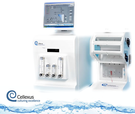
Cellexus CellMaker bioreactor (REGULAR or PLUS).
This is where, with the help of COMSOL Multiphysics, Continuum Blue developed a fully parameterized model of the CellMaker for assessment. A number of parameters in the model were chosen for optimization based on ease-of-adjustment and options available for manufacture (see schematic below), including:
- Number of Flow Ports (n)
- Flow Rate
- Gas Mixture (% O2, CO2, & N2)
- Head (fluid height in bag chamber)
- Geometric properties (A, B, C, etc.)
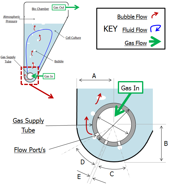
Schematic of section through bioreactor bag and parameters for assessment.
The model we developed was then validated against physical test data. Physical test data included the aspect ratios (AR) and equivalent circular diameters (ECD) of the bubbles formed in the bioreactors under various flow conditions and settings. This bubble data was obtained by taking high-speed video footage and performing image analysis on the bubble formation and flow for over 20 individual bioreactor settings, two of which are presented in the animation below.
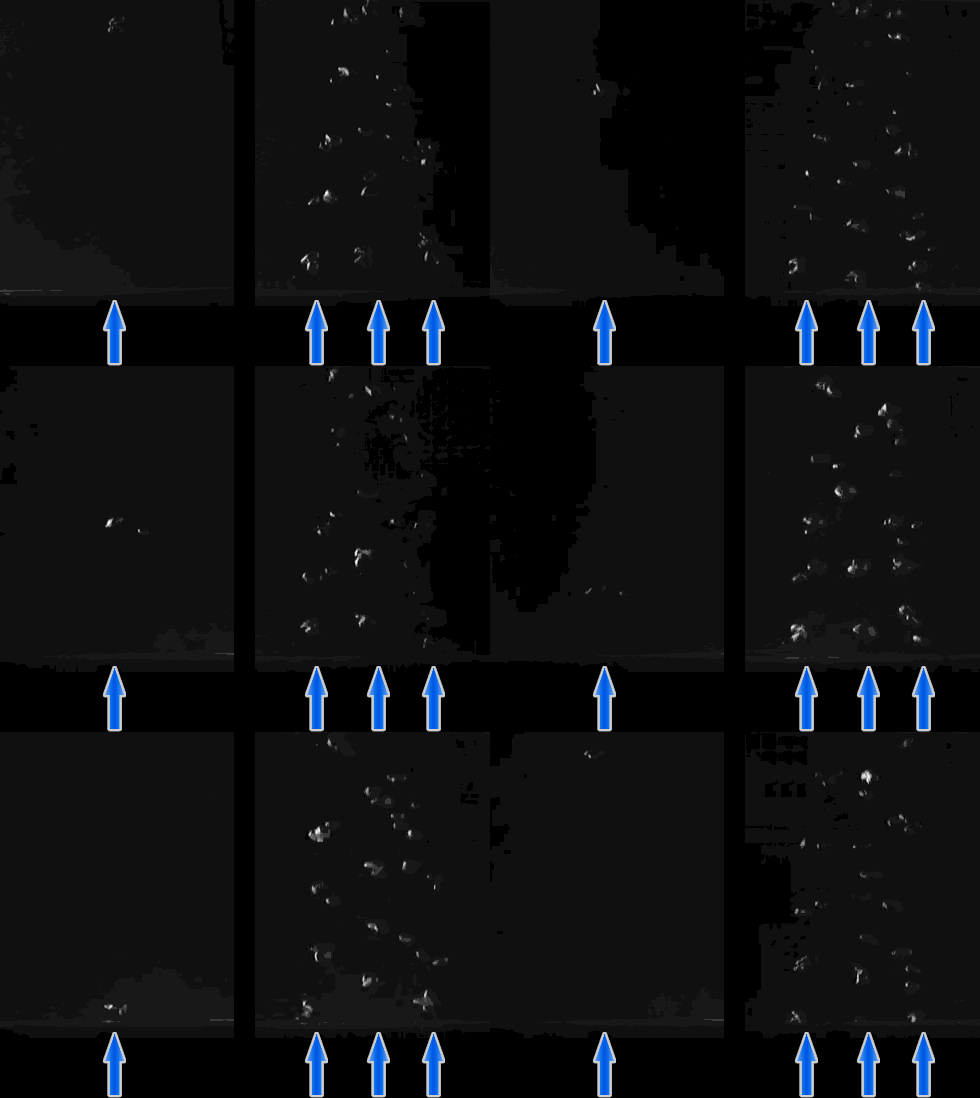
High-speed video footage of bubble formation for two bioreactor settings used to obtain physical ECD and AR bubble data.
Below you can see a graphical representation of the close comparisons obtained from the COMSOL models following validation versus the physical test data for two sets of bioreactor parameters:
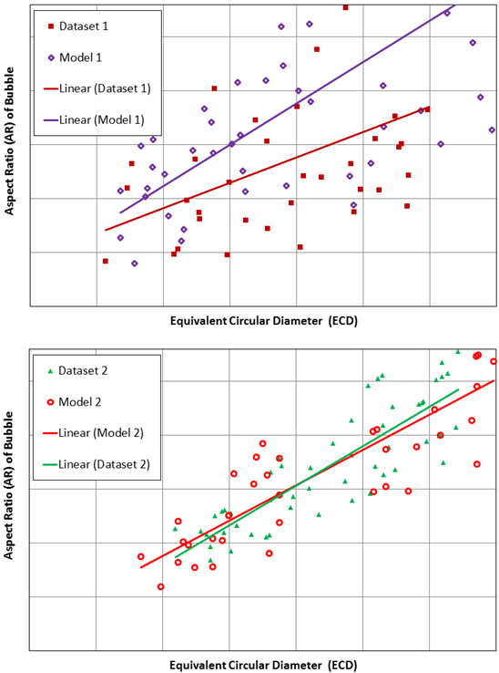
Comparison of bubble ECD and AR for COMSOL model vs. physical test data obtained for two bioreactor settings.
Based on thework by Chisti on sparged bioreactorsand the empirical equations on bubble formation frequencyobtained from Goda et al., it is estimated that as the bubbles break the surface, they should have a diameter of less than 7 millimeters to reduce cell death. Using this target maximum bubble diameter, sweeps on the COMSOL model parameters were performed on the model until solutions were found that reduced the ECD as the bubble broke the surface to between 7 and 20 millimeters, and an AR close to 1, which represents an ideal sphere.
From there, we found several model solutions, and of these we selected a single solution based on ease-of-production and the cost of manufacture. Below, you can see the AR and ECD values for the selected solution:
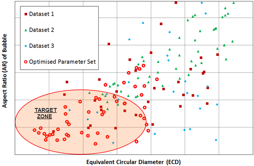
Bubble ECD and AR values obtained from optimized solution vs. three previous bioreactor settings results.
The figure compares the optimized AR and ECD values to those of previously obtained physical test data. Finally, below is the model solution we obtained, with two bubble airlift inlets and displays the velocity magnitude and the bubbles breaking at the free surface.
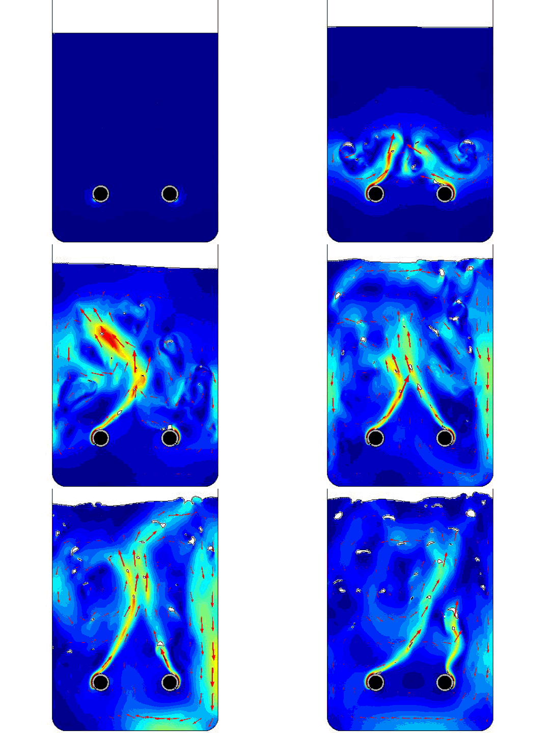
COMSOL model solution with multiple inlet airlift.
About the Guest Author


Comments (2)
Sohan Birla
February 11, 2016Hi Mark, Would please share what physics module ( Bubbly vs phase field flow) were used to simulate the aeration process.
Mark Yeoman
February 12, 2016Hi Sohan, we used the CFD physics module & the Turbulent Two-Phase Flow & Level Set method {tpf}. I hope this helps.