In the world of bearings, there are many different types to choose from. For certain applications, magnetic bearings trump their mechanical counterparts in several regards. In order to understand how the bearing will perform, using a simulation tool to calculate design parameters is a good idea.

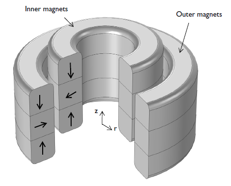
An axial magnetic bearing using permanent magnets. The axial and radial direction are represented by z and r-axes respectively. The magnetization direction of the permanent magnets is shown as black arrows.
When to Use Magnetic Bearings
If you want one part of a machine to support another part, and still allow rotation or linear movement, you will need to use what’s called a bearing.Bearings can be either mechanical or magnetic, and there are many different categories within these two as well, including plain, fluid, flexure, etc. For example, fluid bearings use gas or liquid to carry the load, while flexure bearings utilize a bending load element to support motion. In the case of magnetic bearings, the load is of course instead carried by a — you guessed it — magnetic field.
In other words, magnetic bearings support loads via magnetic levitation. Reducing friction is important for efficiency and safety reasons, so you can imagine that providing load-support without physical contact is very beneficial. Magnetic bearings operate with very low friction and without mechanical wear while also supporting almost limitless speeds (there is no known max relative speed for magnetic bearings!). Many magnetic bearings use permanent magnets for carrying the static load, and are so referred to as “permanent magnet bearings”. Permanent magnet (PM) bearings are used in a variety of machinery, including generators, pumps, flywheel energy storage systems, and more. The use of PM bearings is especially beneficial in flywheel storage systems as they can operate without lubrication, a desirable trait considering that the bearings operate in a vacuum in this case.
Simulating a Permanent Magnet Bearing
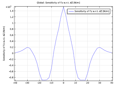
Just as there are different types of bearings, there are also a variety of motions these can exhibit: axial rotation, spherical rotation, linear motion, or hinge motion. Again, the purpose of incorporating a bearing will dictate what motion is most appropriate. For those of you who are interested in calculating design parameters for axial PM bearings, we have a great model in our Model Gallery that shows you how to do just that. The model computes important design parameters such as magnetic forces (radial and axial) and stiffness as a function of the axial displacement in the z-direction.
Intrigued? The full model documentation offers instructions on how to create this model. Check out theAxial Magnetic Bearing Using Permanent Magnetsentry in the Model Gallery.


Comments (2)
Adam Klingest
July 6, 2014Very nice.
The axial magnetic bearing tutorial is great, but i wanted to make a similar model in 3D so that I could calculate the force when the bearing was displaced in the radial axis. But it seems like I can’t apply the same method as in the tutorial, when I am trying to calculate the stiffness of the magnet. I use the sensiitivity and deformed geometry physics, in the same way as in the tutorial, but the calculations won’t converge. Do you have any idea about how I can calculate the stiffness with similar model in 3D?
Regards
Adam
Nirmal Paudel
April 18, 2016 COMSOL EmployeeHi Adam,
The following blog post discuss the magnetic stiffness calculation in 3D. It also include the example model file for your reference.
https://www.comsol.com/blogs/modeling-magnetic-bearings-in-comsol-multiphysics/
Hope this will be useful.
Best Regards,
Nirmal