

TheMembraneinterface has undergone a number of changes with the release of COMSOL Multiphysics version 5.0. This includes a restructured menu, new feature nodes, improvements to the Linear Elastic Material model, and support for the Hyperelastic Material model. You might remember the Nonlinear Structural Materials model Inflation of a Spherical Rubber Balloon. We have now rebuilt it using theMembraneinterface. I will discuss these changes and the new model in today’s blog post.
Linear Elastic Material Model
To begin, I would like to highlight several changes in the Linear Elastic Material model of theMembraneinterface.
First off, the previous version of the interface always assumed geometric nonlinearity. The new version listens to the “Include geometric nonlinearity” setting in the study step settings in the same way as theSolid Mechanicsinterface. The geometric linear version of the membrane can be used when it is acting as cladding on a solid surface. If the membrane is used by itself and not as a cladding, a tensile prestress is, as before, necessary in order to avoid singularity. This is because a membrane without stress or with a compressive stress has no transverse stiffness. To include the prestress effect, you must enable geometric nonlinearity for the study step.
Another update is that linear elastic materials can now also be orthotropic or anisotropic. This affects the settings of the Damping subnode as well, where non-isotropic loss factors are now allowed.
You may also notice that we have added a Hygroscopic Swelling feature as a subnode to the Linear Elastic Material node. (We described thehygroscopic swelling effectin a previous blog post. Check that out to learn more about the effect.)
Hyperelastic Material Model
All of you who use the Nonlinear Structural Materials Module may now use theMembraneinterface to model thin hyperelastic structures by adding a Hyperelastic Material node. In order to illustrate the Hyperelastic Material model using theMembraneinterface, we have recreated the Model Library example Inflation of a Spherical Rubber Balloon.
Tip: You can download the new version of the model in theModel Galleryby logging into your COMSOL Access account.
TheMembraneinterface works on the plane stress assumption, and it is assumed that there is no variation across the thickness of the balloon. Also, it requires a prestress to solve the model due to the absence of bending stiffness in the membrane. For this purpose, a separate study has been created before the inflation of the balloon is carried out in further studies. Results from this analysis are used as initial values for the rest of the inflation analyses. Aside from these two changes, the model is similar to the previous Solid Mechanics version.
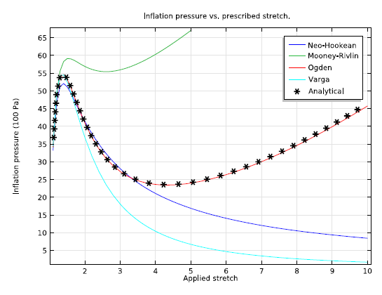
The advantage of the Membrane version is that it is more computationally efficient. Why is that? Because theMembraneinterface is on one geometric entity lower than theSolid Mechanicsinterface. The results obtained from theMembraneinterface are in agreement with the analytical results. The plot below shows the inflation pressure as a function of circumferential stretch for different hyperelastic material models compared to the analytical expression for the Ogden model.
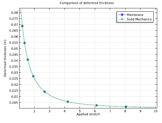
As the internal pressure increases, the balloon starts to inflate and its thickness decreases. Since the pressure is uniform over the surface, the thickness is the same along the cross section for any given inflation pressure. The next plot compares the variation of deformed thickness with applied stretch to the balloon obtained from theMembraneinterface and theSolid Mechanicsinterface. We see that the thinning of the balloon is accurately captured by theMembraneinterface.
Feature Nodes
We have added four new feature nodes to theMembraneinterface.
They are as follows:
- Prescribed Velocity— Available at the domain and boundary level
- Prescribed Acceleration— Available at the domain and boundary level
- SymmetryandAntisymmetry— Both available at the boundary levels
General Changes that Affect the Membrane Interface
In addition to the specific improvements I just went over, we have made a few general changes to the structural mechanics interfaces that affect theMembraneinterface. You will notice that the menus have been restructured for a number of structural mechanics interfaces.
The following interfaces now have restructured menus:
- Solid Mechanics
- Shell
- Plate
- Membrane
- Beam
- Truss
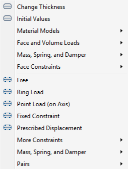
You can see a screenshot of the menu structure for the2D Axisymmetric Membraneinterface below:
As for the Spring Foundation features, we have generalized these so that you can enter the “spring force versus displacement” and the “damping force versus velocity” relations in matrix form, rather than by component.
For 2D Axisymmetric cases, there is a new load type called “Point Load (on Axis)”. With this option, it is now possible to apply loads on a point on a symmetry axis.
For 2D Axisymmetric cases, a Point Load is actually a line load (N/m) since a point represents a ring in axisymmetry. To follow better naming conventions, such a load is now called “Ring Load” in both theSolid Mechanicsinterface and theMembraneinterface.
Backward Compatibility for Earlier Model Versions
Models that were made with COMSOL Multiphysics version 4.4 or earlier still use the oldMembraneinterface and new functionality is not available. To utilize the new functionality for old models, we suggest that you add a newMembraneinterface and copy all the nodes from the previous interface to the new one.
As always, do not hesitate tocontact usif you have any questions.

Comments (0)