
I recently had the pleasure of preparing a small contribution to the 166thMeeting of the Acoustical Society of America (Fall 2013) together with Wade Conklin and Jordan Schultz from Knowles Electronics. Wade presented our paper entitled “Characterization of a microelectromechanical microphone using the finite element method”. The work consisted of implementing a virtual prototype of a Knowles MEMS microphone (the SPU0409LE5H microphone, see picture below) using COMSOL Multiphysics.
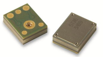
The Knowles SPU0409LE5FH MEMS condenser microphone with dimensions 3.76 x 3 x 1.1 mm3. Photo courtesy ofKnowles Electronics.
What is a MEMS Microphone?
A MEMS microphone is a condenser microphone that comprises a MEMS die and a complementary metal-oxide-semiconductor (CMOS) die combined in an acoustic housing. The CMOS often includes both a preamplifier as well as an analog-to-digital (AD) converter. Because of this and the small size of the microphone, it is well suited for integration in digital mobile devices, smart phones, headsets, and hearing aids. The housing with the acoustic port is depicted in the image above. The condenser or variable capacitor consists of a highly compliant diaphragm in close proximity to a perforated, rigid backplate. The perforations permit the air between the diaphragm and backplate to escape. The diaphragm and backplate pair is referred to as the motor (shown in the figure farther down below). The microphone works by first polarizing (charging) the condenser with a DC voltage. This voltage will also result in a static deformation and tensioning of the diaphragm, and, to a much less extent, the backplate. When an acoustic signal reaches the diaphragm through the acoustic port, the diaphragm is set in motion. This mechanical deformation in turn results in an AC voltage across the microphone. These effects combine to provide a real multiphysics problem well suited for analysis in COMSOL Multiphysics. The sensitivity of a microphone is expressed as the ratio of the incident pressure to the measured voltage on the dB scale.
About the Knowles MEMS Microphone Virtual Prototype
The MEMS microphone model includes a description of the electrical, mechanical, and acoustical properties of the transducer. The acoustic description includes thermal and viscous losses explicitly solving the linearized continuity, Navier-Stokes, and energy equations, that is,thermoacoustics. The mechanics of the diaphragm were also modeled including electrostatic attraction forces and acoustic loads, orelectromechanics. Asubmodelwas also implemented to analyze the interplay between the vibrating diaphragm and the small perforations in the microphone backplate. The model had no free-fitting parameters and it resulted in the prediction of the static mechanical behavior of the MEMS motor (the diaphragm and backplate system) as well as the dynamic frequency response. The model results showed good agreement with measured data.
Modeling with the Acoustics and MEMS Modules
Because the geometrical dimensions are so small in this system, the vibrations of the diaphragm will be highly damped by the air. The air and acoustics need to be treated including both thermal conduction and viscous losses. The viscous penetration depth (thickness of the acoustic viscous boundary layer) is, for example, 55 µm at 100 Hz and 5.5 µm at 10 kHz, which is larger than or comparable to the distance between the backplate and diaphragm, which is only 4 µm. TheThermoacousticsinterface of theAcoustics Moduleis the natural first choice for modeling these effects. This interface will also result in the correct modeling of the transition from adiabatic to isothermal behavior at low frequencies. The complex combined mechanics and electrostatics effects are all included in theElectromechanicsinterface of theMEMS Module. The two physics are fully coupled at the fluid-structure boundary by requiring continuity in the displacement/velocity field.
As a MEMS microphone makes out a complex system, we faced several challenges when trying to model it in detail. Some of these included:
- During the clean room MEMS fabrication process, the diaphragm is released and will bend slightly
- It is important to give a correct description of its initial shape and stress distribution
- The geometry of the microphone is complex, involves many different aspect ratios, and small length-scales
- Thinking about the mesh is important
- Because the system is complex and involves many different physics, the resulting model can easily become too large to solve
- Reducing the model by using symmetries and lumped approximations also needs to be addressed
A classical condenser microphone, like theB&K 4134 from the Model Gallery, in essence works the same way as the MEMS microphone and involves solving the same physics. Modeling it, however, involves some specific challenges as mentioned above. They are primarily due to the complex fabrication involved and lie in describing the initial static state and the complexity of the geometry.
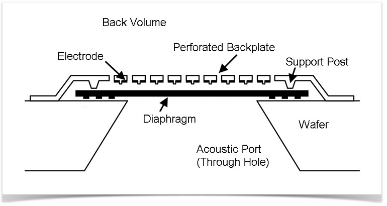
Sketch of the MEMS microphone motor (not to scale). The diaphragm has a thickness of 1 µm, the gap between the backplate and the diaphragm is 4 µm, the diameter of the perforations in the backplate is 10 µm, and the thickness of the backplate is 2 µm. The distance across the motor from support post to support post is 590 µm. Sketch courtesy ofKnowles Electronics.
Some COMSOL Model Results
As a first step when planning the modeling process, we decided to focus on validating the initial stationary description of the model. One direct measurement of the stationary shape of the microphone is achieved by measuring the DC capacitance as a function of the polarization voltage. The measurements are compared to the model results in the figure below. As you can see, the two curves show good agreement. At about 15.8 V, the measured curve is seen to jump. This corresponds with the point where the diaphragm bends so much due to the electrostatic forces that it touches the backplate.
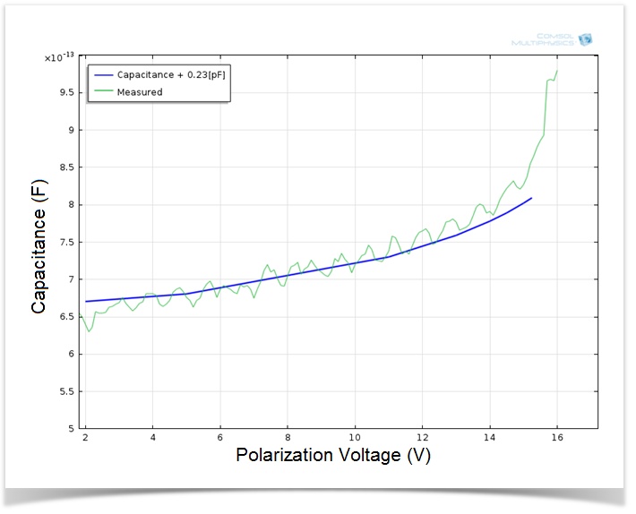
Simulation results of the microphone static capacitance as a function of the DC polarization voltage. Thegreencurve represents measurements and thebluecurve the modeled capacitance including a constant offset accounting for the constant parasitic capacitance present when performing measurements (0.23 pF). Measurements courtesy ofKnowles Electronics.
The electric potential in slices through a 30 degree cut-out of the microphone motor is depicted in the image below. The field is seen to have very strong gradients in the region where the electrodes are located, while it drops off outside of this region. The holes in the backplate are clearly seen to influence the field. The full dynamic behavior of the microphone was also analyzed solving for the structural displacement, the electric field, and the thermoacoustic fields (pressure, velocity, and temperature) in the frequency domain. This is a fully coupled multiphysics model in a complex geometry and therefore required up to 60 GB of RAM to solve. The resulting sensitivity also showed good agreement with measurements.
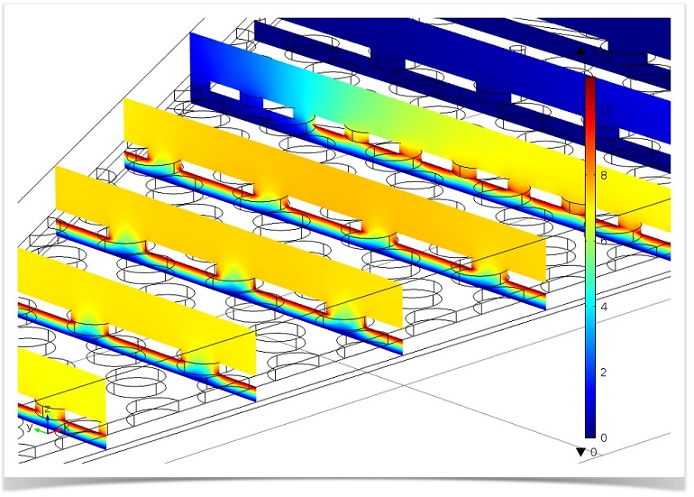
Stationary electric potential depicted in slices through the MEMS microphone motor.
A unit cell of the diaphragm and backplate system is shown in the below animations. The model represents one hole and the air gap (thin air film) between the vibrating diaphragm and the backplate (here fixed). This system is analyzed as a unit cell using symmetries. The detailed coupled acoustic behavior including viscous and thermal losses is again captured using thethermoacousticsinterface. The two animations show the behavior of the instantaneous acoustic velocity distribution and temperature distribution at 10 kHz over one period. The model also solves for the pressure (not shown here). The build-up and decay of both the thermal and viscous boundary layers can be seen in the animations. At 10 kHz, the thickness of both is about 5 µm and is comparable to the air gap height of 4 µm.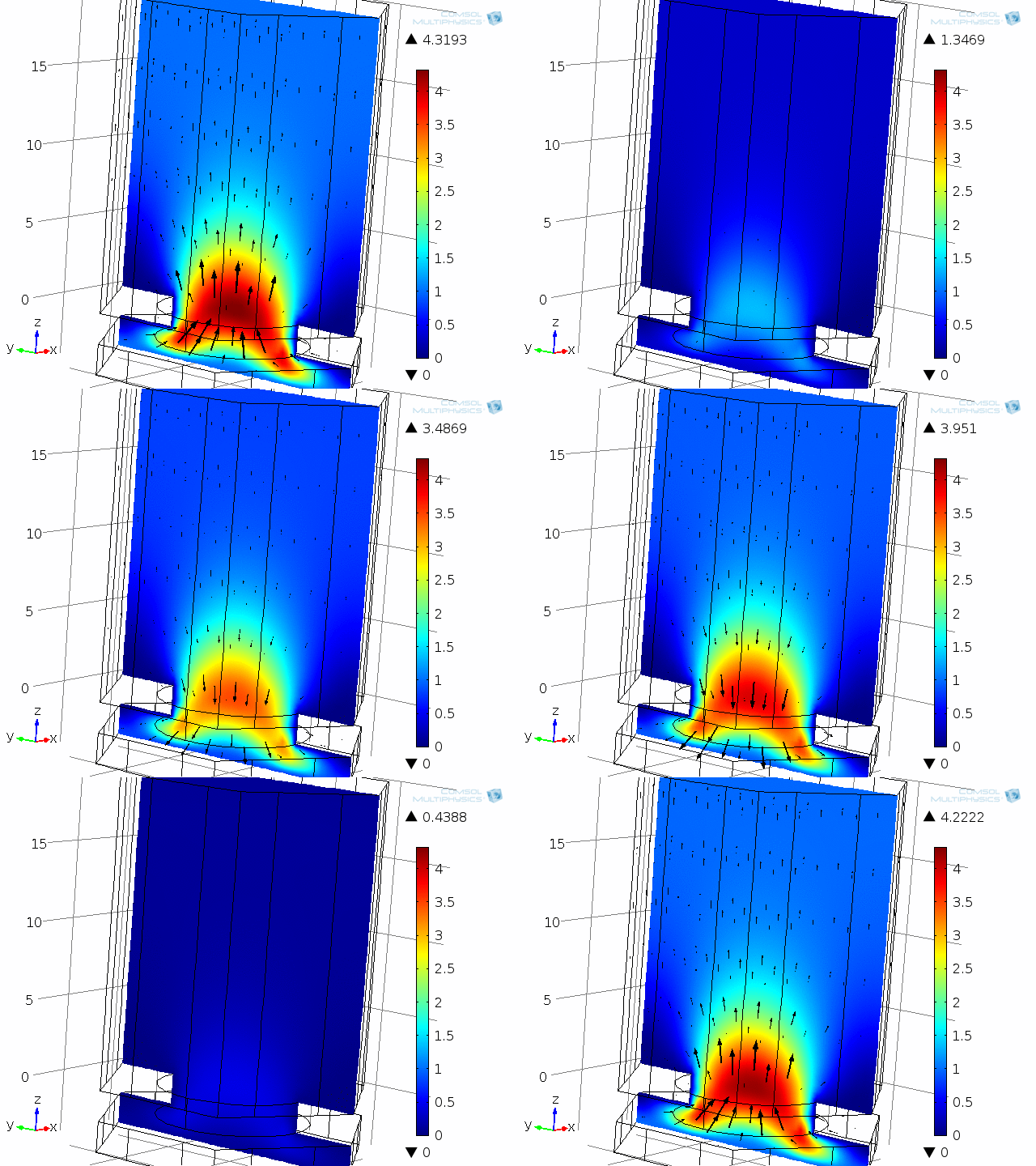
Dynamic analysis of one “unit cell” of the diaphragm and backplate system, here modeled at 10 kHz. Shown here are the instantaneous acoustic velocity magnitude (color) and velocity field (vectors).
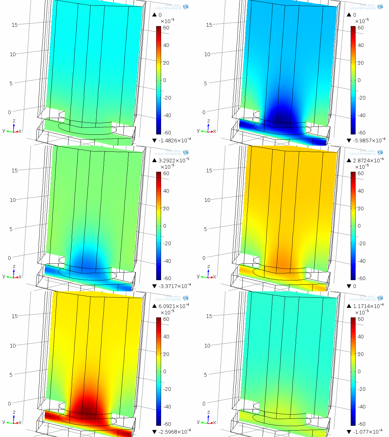
Dynamic analysis of one “unit cell” of the diaphragm and backplate system, here modeled at 10 kHz. The acoustic temperature variations are depicted in this animation.
Further Reading
- M. J. H. Jensen, W. Conklin, and J. Schultz,Characterization of a microelectromechanical microphone using the finite element method, J. Acoust. Soc. Am.,134, pp. 4122 (2013) (Conference abstract)
- B&K 4134 Condenser Microphone modelin the Model Gallery
- Knowles Electronics
- Acoustics Module
- MEMS Module
- P. Loeppert and S. Lee,Sisonic–the first commercialized MEMS microphone, Solid-state sensors, actuators and microsystems workshop, Hilton Head Island, South Carolina, pp. 27–30 (2006)


Comments (0)