Last month, my colleague Alexandra Foley introduced anRF modeling example that uses periodic boundary conditions. Another RF model that can be created with ease by taking advantage of periodic boundary conditions is the Frequency Selective Surface, Periodic Complementary Split Ring Resonator model.
About Frequency Selective Surfaces (FSS)
Frequency selective surfaces (FSS) are periodic structures that function as filters for plane waves, such as microwave frequency waves. These structures can transmit, absorb, or reflect different amounts of radiation at varied frequencies. Typically, they have a bandstop or bandpass frequency response.
Frequency selective surfaces are used in a variety of applications. For example, the article “Picking the Pattern for a Stealth Antenna” fromCOMSOL News 2013describes how engineers at Altran used FSS as RF filters to reduce the radar cross sections (RCS) of stealth antennas. In the article, designers employed FSS to reduce antenna gain in order to lower the RCS. There, the FSS were designed to absorb incident radiation, rather than scatter it. FSS surfaces are typically constructed with metallic patterns that are arranged periodically. Complementary split ring resonators can be used to build such structures.
Complementary Split Ring Resonators
As a type of planar resonator, complementary split ring resonators are primarily used to simulate metamaterial elements. When designing a bandpass structure, for example, they can be arranged periodically. Modeling these resonators in a periodic configuration can become quite complex and time consuming. However, you can overcome these design challenges by implementing periodic boundary conditions into your model.
Modeling a Periodic Complementary Split Ring Resonator
COMSOL Multiphysics, together with theRF Module, enables you to model a periodic complementary split ring resonator with ease by utilizing perfectly matched layers and periodic boundary conditions. As an example, we can refer to theFrequency Selective Surface, Periodic Complementary Split Ring Resonatormodel, which is available in our Model Gallery.
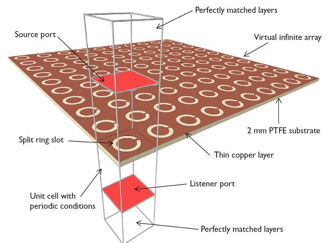
In this model, a split ring slot is patterned on a thin copper layer (which is modeled as a perfect electric conductor) that rests on a PTFE substrate that is 2 mm in thickness.

A single unit cell of the complementary split ring resonator. The model is created with periodic boundary conditions.
To simulate a 2D infinite array, as shown above, you can model just one unit cell of the complementary split ring resonator. This is done using Floquet-periodic boundary conditions on each of the four sides of the unit cell.
To learn how to do this,check out the model documentation, where step-by-step instructions are provided.
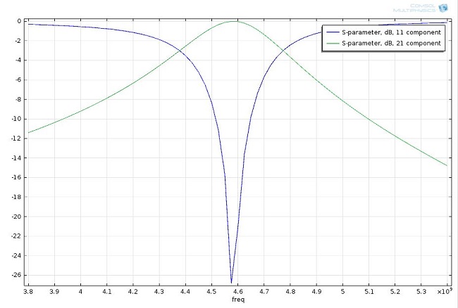
While this post mostly focuses on how you can save time modeling using periodic boundary conditions, this particular model’s documentation goes into further detail regarding the periodic structure’s bandpass frequency response in terms of S-parameters, as shown below.

S-parameter plot showing the periodic structure functions as a bandpass filter near 4.6 GHz.


Comments (2)
Alhuda Moujaly
February 9, 2015please I need tutorial about how I can design ring resonator in comsol
kemerov kreshna
June 27, 2021I want to simulate the same problem,but i assume that the metallic parts are thick (IBC use)
How do i do that?