

To accurately compute lift and drag forces and optimize any airfoil following the NACA naming convention, COMSOL Multiphysics version 5.2 includes a new example, the NACA Airfoil Optimization app. In this blog post, we discuss how the app can be used for production applications and how you can benefit from using the Application Builder to enhance your own models and apps.
Lifting off the Ground and into the Skies
On a windy December morning in 1903, the Wright brothers prepared to make an attempt at flight in Kitty Hawk, North Carolina. Orville Wright took control of the plane and, making history, flew for 12 seconds across a distance of 120 feet. This groundbreaking moment marked the world’sfirst successful powered flight.
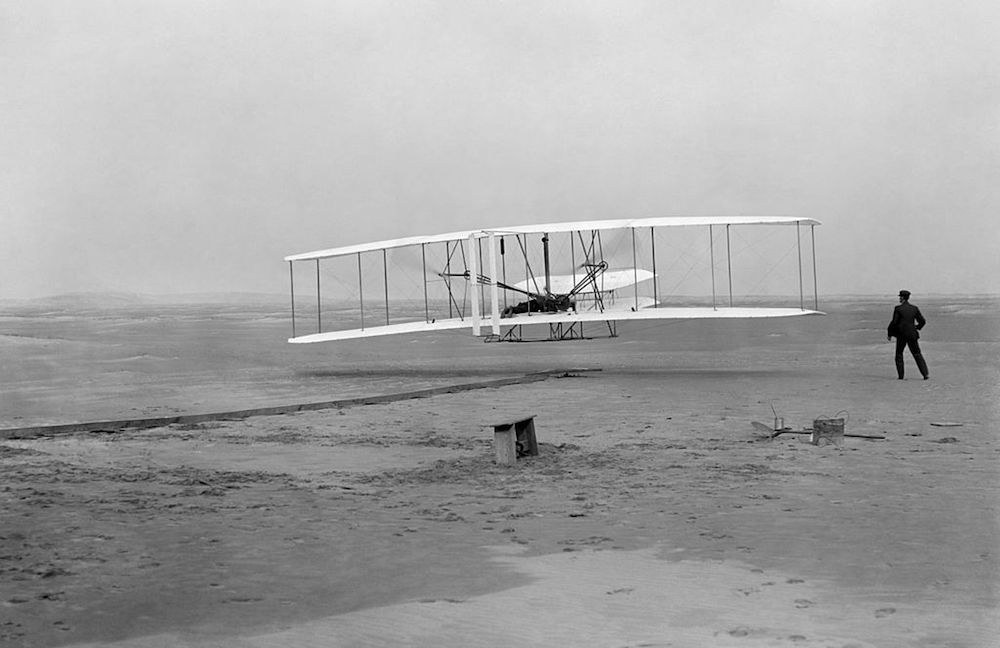
The Wright brothers were aviation pioneers, flying the first powered airplane in 1903.
Since that time, we have continued to take to the air, with airplanes growing in size and strength. While modern airplanes may fly much farther than the Wright brothers’ plane, they still obey the same laws of physics. A force known asliftholds airplanes aloft by opposing the weight of the airplane, thus enabling these machines to soar high above the ground.
By being able toeasily compute lift and drag forceson an NACA airfoil with a customized simulation app, we can optimize these designs for aeronautical applications. Let’s get started…
The Capabilities of the NACA Airfoil Optimization App
The NACA Airfoil Optimization app allows for the computation of the lift and drag forces on a fully parameterized NACA airfoil. Thefour-digit NACA airfoilis an airfoil shape developed by the National Advisory Committee for Aeronautics (NACA), the precursor to the National Aeronautics and Space Administration (NASA).
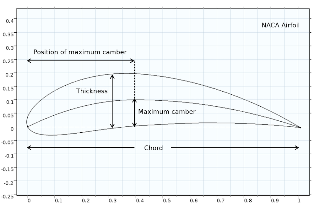
The basic geometry of an NACA airfoil.
The naming convention for the airfoil is as follows:
- The first digit describes maximum camber as a percentage of the chord.
- The second digit describes the distance of maximum camber from the airfoil’s leading edge in tenths of the chord.
- The last two digits describe the maximum thickness of the airfoil as a percentage of the chord.
The NACA 2412, for instance, is an airfoil with a maximum camber of 2%, located at 40% of the leading edge. Its maximum thickness is 12% of the chord. The NACA 2412 is the default airfoil in this app.
The airfoil geometry is fully parametric and the app incorporates theOptimizationinterface to find the wing geometry parameters that maximize the lift-to-drag ratio.
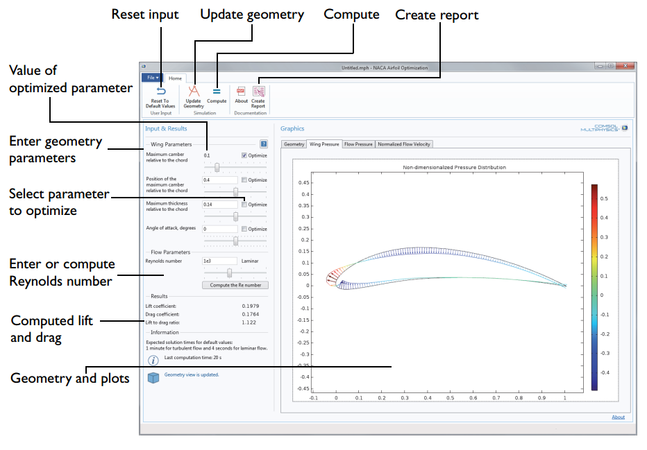
The app’s user interface.
You can choose to enter the airfoil parameters andReynolds numberdirectly, or let the app’s optimization solver find the right geometry parameters to maximize the lift-to-drag ratio. The app computes and displays the flow velocity and pressure, the lift and drag coefficients, as well as the optimized geometry and its parameters.
Use the Application Builder to Enhance Your NACA Airfoil Designs
COMSOL Multiphysics has a user-friendly interface, but building an airfoil model can still be a complex task. As the modeling engineer, you have to build the geometry and select the right fluid flow interface based on theflow regime. If the flow is turbulent, you also need to select the rightturbulence model. This process requires both time and simulation expertise.
With the NACA Airfoil Optimization app, building the geometry, choosing the correct fluid flow interface, and postprocessing are already taken care of when you design the app. The resulting app can therefore be deployed to your colleagues and customers for production uses.
Because the geometry is fully parameterized, the app can model any NACA wing geometry. The same is valid for the flow regime: The appropriate fluid flow interface is automatically chosen by the app based on the Reynolds number. Low Reynolds number simulations are performed on a coarse mesh with theLaminar Flowinterface. Higher Reynolds number simulations use the Spalart-Allmaras turbulence model, which has been specifically developed for airfoil simulations. Both of these fluid flow interfaces allow for accurate computation of the lift and drag forces.
The app user specifies the flow regime in the app through the Reynolds number. Since the app is meant for a nonspecialist who might not be familiar with the Reynolds number, theCompute the Re numberbutton allows the user to calculate the Reynolds number based on wing chord length, wind or flow speed, as well as fluid density and viscosity.
While the Application Builder and COMSOL Server™ are initially meant to manage and deploy your simulations, you can also use the Application Builder to extend the capabilities of the Model Builder for your own needs. The Application Builder and the included Method Editor allow for easy access to the COMSOL API. For the NACA Airfoil Optimization app, the API is used to create a plot that can’t be built automatically in the Model Builder.
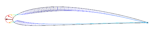
Pressure distribution on the airfoil, plotted using the Method Editor and COMSOL API.
Get Started Building CFD Simulation Apps
Open the NACA Airfoil Optimization example app, explore its functionality, and use the same methodology to build your own apps. This particular example teaches you how to create an app that can optimize the airfoil geometry for a given objective, automatically switch physics interfaces and meshes based on user input, and create advanced plots for easy postprocessing.
There are many more ways that you can benefit from the Application Builder and COMSOL Server™. You could use this app for teaching purposes and use the pressure distribution plot to explain to your students how the pressure difference on both sides of the airfoil creates an upward lift. The students could then test different airfoil parameters to try to improve the wing design and get some physical understanding of the lift without having any CFD background. Additional ways to use the Application Builder are detailed in thisprevious blog post.
Try It Yourself
- Download theNACA Airfoil Optimizationexample app

Comments (0)