The chemical industry is considerably important to economies around the world, playing a critical role in processes ranging from the production of clean drinking water to the manufacture of pharmaceutical products. Chemical engineers are faced with the challenge of ensuring profitability in a rapidly growing and evolving market. Packed bed reactors are one of the most common reactors used in the chemical industry due to their high conversion rate per catalyst weight compared to other catalytic reactors.
How a Packed Bed Reactor Works
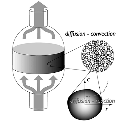
Packed bed reactors are very versatile and are used in many chemical processing applications such as absorption, distillation, stripping, separation processes, and catalytic reactions. Across the diverse applications in which they are used, the physical dimensions of the beds can vary greatly. Typical reactors consist of a chamber, such as a tube or channel that contains catalyst particles or pellets, and a liquid that flows through the catalyst. The liquid interacts with the catalyst across the length of the tube, altering the chemical composition of the substance.
The schematic below shows a simplified design of a typical packed bed reactor:
Design Challenges of Packed Bed Reactors
When designing a packed bed reactor, the design must includemass transfer(or species transport) in the bed as well as heat transfer and chemical reactions. Understanding and optimizing the heat transfer through packed beds is important in order to decrease the cost of running the equipment. The packed catalyst is also critically important to the successful modeling of the device; the catalyst can be modeled as a porous structure, which leads to particle transport with different orders of magnitude, making the analysis of mass and energy transport a challenging task.
Another challenge when designing these devices lies in the pressure drop that occurs across the length of the reactor. The pressure drop can be reduced by using larger catalyst particles, but this causes lower intraparticle diffusion, making the reaction progress slower. The trade-off here is to find a particle size that is large enough to limit the pressure drop and small enough to allow the reaction to proceed at a fast enough rate. A catalyst particle radius is typically in the order of magnitude of 1 millimeter. The space located between particles is described as macroporous structure of the bed, while pores inside the catalyst themselves form what is known as the microstructure.
Various Applications
Depending on the application at hand, many different variations of the device can be designed. Examples of this could include different temperature and inlet concentration of the reactants, changes that can affect the reaction rate and the conversion that occurs. Additionally, depending on the application, there are many different packing shapes available for packed bed reactors that can affect the rate of the reaction.
Design variables that might change depending on the application: the catalyst diameter (active surface area per unit volume of material), structural strength, constructability, manufacturing cost, micro- and macroporous volume, and transport properties, to name a few.


Comments (2)
Víctor Casquero
August 15, 2014It would be interesting to take out a physical Interfas dedicated to model these phenomena.
Fanny Griesmer
November 3, 2014 COMSOL EmployeeHi Victor,
You can now model this phenomenon using COMSOL Multiphysics version 5.0 — learn more here:http://www.comsol.com/blogs/multiscale-reactors-cleaning-flows/