
Have you been looking for software that can solve the Testing Electromagnetic Analysis Methods (TEAM) Problem 7? We solved the problem with COMSOL Multiphysics and the AC/DC Module. Here are the results.
What Are TEAM Problems?
The Testing Electromagnetic Analysis Methods (TEAM) group formed with the goal of comparing different computer codes for electromagnetic analysis. To do so, the TEAM group meets periodically to come up with benchmark problems. Each set also contains experimental results for validation.
About Problem 7
One of these problem sets,Problem 7, pertains to anasymmetrical conductor with a hole. The scenario involves an aluminum conductor that is arranged asymmetrically over a multi-turn coil, which carries a sinusoidally varying current. This arrangement induces eddy currents and a magnetic field — both of which can be calculated. Problem 7 requires the solver to compute these fields and currents at different positions.
We have created a model to show you how to solve this benchmark problem with COMSOL Multiphysics and the AC/DC Module.
Benchmark Model: Multi-Turn Coil Over an Asymmetric Conductor Plate
To solve Problem 7, we need to compute the eddy currents and magnetic field in the conductor for coil current frequencies of 50 and 200 Hz. If our results at the specified positions match the experimental data, we can draw conclusions about the accuracy of COMSOL Multiphysics.
As we can deduce from the name of the model, the geometry does not contain any symmetries and must therefore be solved in its entirety. Here’s our geometry of the copper coil and aluminum plate:
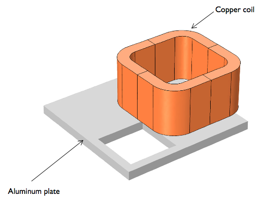
Problem 7: The geometry of the multi-turn coil (2,742 turns) placed asymmetrically over the conductor plate with a hole. The sinusoidally varying current in the coil is 1 A/turn.
Our Results
Using COMSOL Multiphysics and theAC/DC Module, we can simulate our results at the two frequencies. Below, you can see two 3D surface plots of they-component of the induced current density in the plate. Arrows denote the direction of both the coil current (red) and the conductor’s induced current density (black).
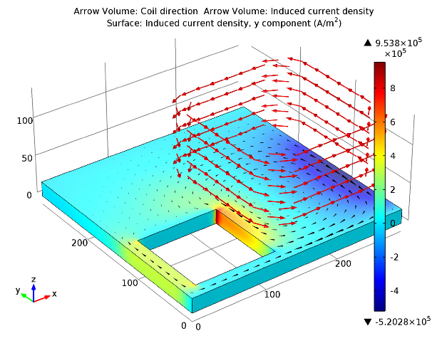
50 Hz.
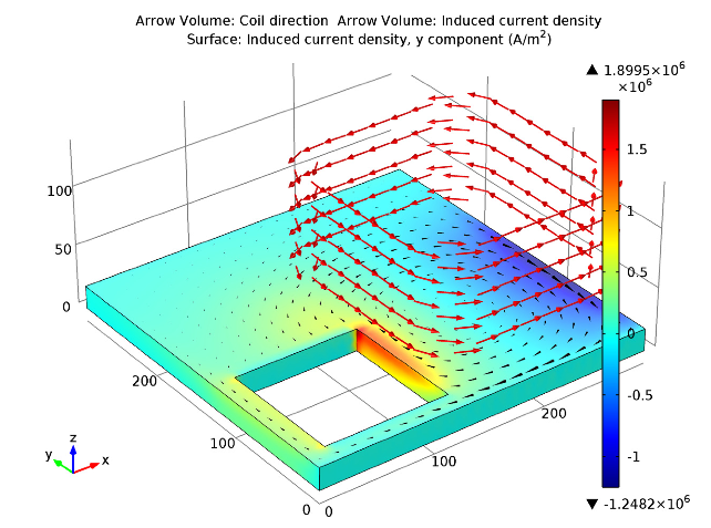
200 Hz.
Now that we have our results, it’s time to compare them with the measured results to see how they match up. Hopefully they do…
Problem 7 Results Comparison
To illustrate how the results compare, we have plotted our simulation (solid) and the experimental results (circles) in two line graphs. The left-hand graph shows the values for the magnetic flux density, while the right-hand graph depicts the induced current densities.
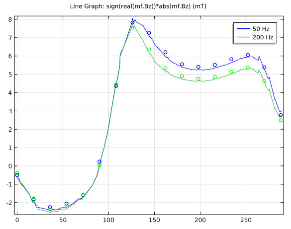
Comparison of results:z-components of the flux density.
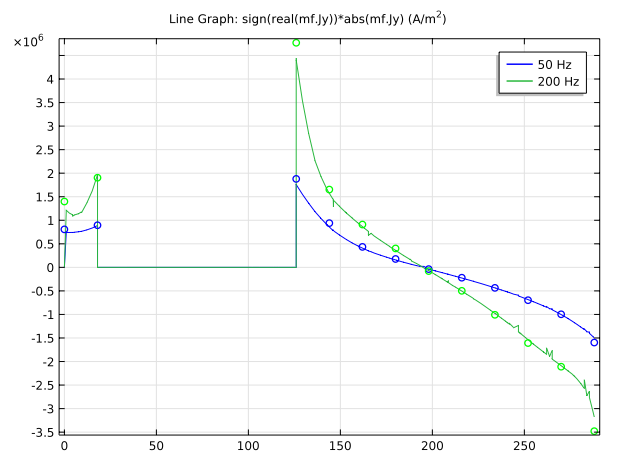
Comparison of results:y-components of the induced current densities.
As we can see, our simulation results agree very well with the experimental results. We have solved Problem 7 according to the TEAM specifications.
Learn How to Build the Model
- Download the model:Multi-Turn Coil Over an Asymmetric Conductor Plate


Comments (0)