
TheWall Distanceinterface is used to calculate the distance to a wall in the turbulent flow interfaces available in COMSOL Multiphysics. It can be combined with any other interface and comes in handy when we need to calculate the distance to the nearest wall or detect, as part of a dynamic model, when a moving object will hit a wall. Today, we will study how theWall Distanceinterface works and how other interfaces can benefit from its capabilities.
How the Wall Distance Interface Works
TheWall Distanceinterface calculates the reciprocal distance to selected walls. The value will be small when the object is far away from the respective walls and larger when closer. The exact distance,D, to the closest wall can be found by solving the Eikonal equation:
whereD=0on selected walls and\nabla D\cdot n=0on other boundaries. COMSOL Multiphysics solves for a modified version of the Eikonal equation, where the dependent variable is changed fromDtoG=1/Dand an additional smoothing parameter,\sigma_w, is used.
This results in the following equation:
withG=G_0=2/l_{ref}on selected walls and homogeneous Neumann conditions on the other boundaries. Here,l_{ref}is a parameter that depends on the geometric shape and is calculated automatically. This parameter can also be defined manually, if necessary.
The resulting wall distance,D_w=1/G-1/G_0, and the direction to the nearest wall are available in COMSOL Multiphysics as predefined variables.
Once we add theWall Distanceinterface to a model, we simply have to add a Wall boundary condition and select the walls from which we want to calculate the distance. Below, you can see an example where we are interested in knowing the distance to the bottom and right-hand walls of a rectangle:
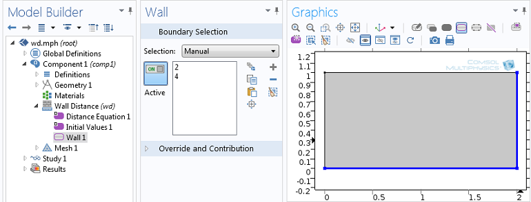
Boundary selection of theWall Distanceinterface.
Next, we plot the reciprocal wall distance,G, and the wall distance,D_w, and the direction toward the nearest wall:
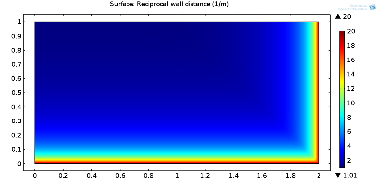
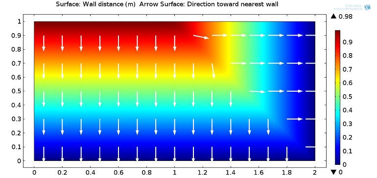
Reciprocal wall distance (top figure) and wall distance with arrows showing the direction towards the nearest wall (bottom figure).
The effect of the smoothing parameter,\sigma_w, can be seen by plotting the wall distance from the top wall to the other two:
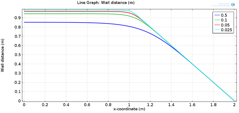
Wall distance at the top wall for different values of the smoothing parameter,\sigma_w.
For the first half of the top wall (xbetween 0 and 1), the distance to the nearest wall is constant, while it decreases linearly forxbetween 1 and 2. By solving the model for different values of\sigma_w, we can see how, for smaller values of\sigma_w, the wall distance is accurately computed. For larger values, there is a loss in accuracy, but a much smoother transition from the constant value to the linear decrease. Depending on the application being modeled, you can choose the value of\sigma_wthat provides the desired accuracy, smoothness, and model convergence.
Combining the Wall Distance Interface with Another Interface
Now we’re ready to combine theWall Distanceinterface with another interface. Let’s consider a flow channel containing a solid object subjected to the action of pressure and viscous stress due to fluid flow and a spring pushing it down. If the sum of the forces acting on the object is zero, it will stay still. If the force of the spring is larger than the fluid pressure and viscous stress, then the object will move down and either reach a new equilibrium position or close the channel.
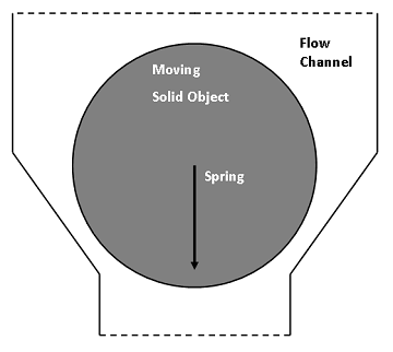
Schematic of the model.
The fluid load on the object is included using the Fluid-Solid Interface boundary condition that comes withFluid-Structure Interactioninterface, which solves for both the fluid and deformable solid domain, as well as their interaction at the boundaries. To reduce the overall model size, we can build a 2D axisymmetric model and represent the spring by a boundary load depending on the position of the object.
The mesh inside the fluid domain is free to move and deform in order to adjust to the motion of the object. The geometric change of the fluid domain is automatically accounted for in COMSOL Multiphysics. In this approach, we’re not interested in the contact forces between the object and the channel walls as we are only investigating how easy it is to couple different interfaces and create custom functions. We will then close the channel by increasing the viscosity in areas where the object is close to the channel walls. Doing so will stop both the flow and movement of the object.
How, then, do we exclusively increase the viscosity in areas where the object is close to the channel walls? You could, of course, leverage user-defined functions. But in this case, you have to know where and when the object will reach the wall and find smooth functions representing this area. To do this, we will use theWall Distanceinterface, which can detect the area and trigger changes in the material settings to increase the viscosity. This will enable the object to move in any direction, but increase fluid viscosity when it is likely to hit any of the walls at any time.
Wall Distance Interface
We will add two instances of the interface: one on the boundaries of the object (with the dependent variable G2) and another on the walls of the channel (with dependent variable G3). Detection is performed through a function that depends on the sum of both variables (G2 + G3).
As we can see in the below screenshots (all using the same color range), the sum of G2 and G3 will be higher if the object is close to the channel wall. The maximum value for each wall distance is 2,667 1/m (left and middle column). Looking at the sum (right column), the maximum depends on the position of the object. In order to allow the increase in fluid viscosity to “stop” the flow and control the mesh deformation, we set a condition that if the channel is open, the maximum is about 4,000 1/m, and if it is closed, the maximum is more than 5,000 1/m.
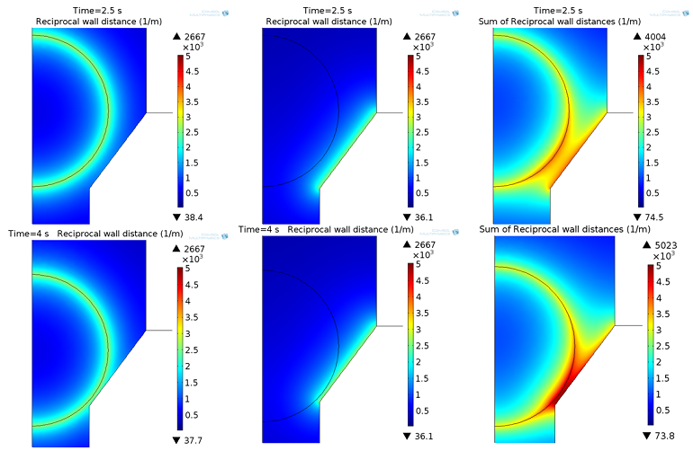
Reciprocal wall distance G2 (left column), G3 (middle column), and sum of G2+G3 (right column) in the opened (top row) and closed (bottom row) state.
Viscosity
The viscosity is now increased in areas where the maximum is more than 5,000 1/m. To improve convergence, the viscosity change that kicks does so through a smooth ramp function. So, we have two parameters: one for the slope of the function and another for the smoothing of the function.
This function is added to the viscosity of the fluid:
![]()
Manipulation of the dynamic viscosity to account for a smooth increase in viscosity due to the wall distance. The equations are entered directly into the interface’s edit field.
You can view the results in the animation below. The viscosity of water is about 1×10⁻³Pa*s (blue in color), while areas with a viscosity higher than 1 Pa*s are red in color.
Fluid viscosity change over time and dependent on the distance between the object and wall.
Results
We start with a zero pressure at both the inlet and outlet, and place the object in the closed position at the beginning. A time-dependent function is used to vary the inlet pressure. We will increase the pressure for a short period of time to see how the object reacts to this pressure. In the following animation, we can see both the flow in the channel with the moving object and the inlet pressure, which varies between 0 and 2 mbar. In addition, you can see the resulting mass outflow of the outlet (top boundary).
Streamline plot of the velocity field with its magnitude represented as the color expression (left). The imposed inlet pressure (blueline) and mass flow at the outlet (greenline) are shown in the right figure.
We can see that there is a small time delay between the pressure increase and the opening of the channel due to the inertia resulting from the spring. If the pressure is too small, the object will not move and the channel stays closed. After opening the channel and then decreasing the pressure, the channel closes and the outflow returns to zero.
Conclusion and Next Steps
We started with the settings of theWall Distanceinterface and added a wall boundary condition to select the walls of interest. As we saw in the example, theWall Distanceinterface can be combined with any other interface. We used it to detect the areas where a moving object is close to the walls.
If you want to learn more about modeling with theWall Distanceinterface, do not hesitate tocontact us.


Comments (6)
daniyar bosinov
March 29, 2016Hello!
Have a nice day!
Can you send me your mph file?
Adam Lee
June 28, 2016Very interesting!
Recently, I want to model the “Hydrodynamic Flow in Microfluidic Biochip for Single-Cell
Trapping Application”.
When the cell is trapped in the gap zone(the cell which diameter is bigger than the gap, get stuck in a “trapped gap” as web shows ),the cell particle is close to the channel wall,and the distance to the wall gets smaller.
So,I don’t know how to handle the “Wall-cell interaction” except “Automatic remeshing”,but the mesh size gets extremely smaller,leading to the very large grid number ,and COMSOLs always hint me” Out of memory during LU factorization”.
Fortunately, the solution that “fluid viscosity changes with the wall distance ” as the web described, seems a good news to me.And I have read the “help”:
1.Add physics “Wall distance”, define the fluid zone, boundary zones;(G2,Reciprocal wall distance to the microchannel trapped gap wall)
2.Build the “Wall distance” of the solid zone, and define boundary zones;(G3,Reciprocal wall distance to the cell boundary)
3.User define the dynamic viscosity with the ramp function of G2,G3,such as
rm1(G2[m]+G2[m])[Pa*s]+mu_fluid ,mu_fluid formerly defined as a local variable represents the dynamic viscosity of the water.
4.The other setup and start computing!
So is it alright? Need your advises!
Another questions:
when I add physics “wall distance” of the solid and fluid zone ,and without the function of G2
,G3,everythings seems OK;But with the function, Comsol always says “Failed to find consistent initial values.”
Looking forward for your reply!
Clemens Ruhl
June 28, 2016 COMSOL EmployeeHello,
Thank you both for your comments and interest in this blog post!
For your questions, please contact our support team.
Online support center:https://www.comsol.com/support
Email:support@comsol.com
Best,
Clemens
Raymond Yeung
April 20, 2018Can COMSOL’s FSI interface handle contact between a solid object and the walls of the fluid domain? I have been having issues with convergence due to the topology change once the solid object collides with a wall boundary.
I tried incorporating the wall distance interface into an already-working time-dependent model with automatic remeshing as the solid object traverses through the fluid domain, but I have also run into issues of ‘failing to find consistent initial values.’ I tried a simple stationary case with a rectangle as described from your blog to test the wall distance interface and had no issues.
Would appreciate any suggestions or tips regarding how to address the contact issue in the FSI interface!
Abdullah Bahlekeh
February 26, 2020Hi,
could you please to support with any application model or tutorial regarding the “Wall Distance Interface” ?
Best Regards
Abdullah Bahlekeh
February 26, 2020Hi,
could you please to support with any application model or tutorial regarding the “Wall Distance Interface” ?
Best Regards