
Today, we introduce guest blogger Bernd Baumann, who shares insight into optimizing the performance of metal-halide lamps with simulation, with input from his colleague Joerg Schwieger.
With the help of COMSOL Multiphysics, we investigated the impact of acoustic resonances and the related acoustic streaming field on the operation of metal-halide discharge lamps. To our surprise, we found that the lamps exhibit behaviors that are similar to a well-known mechanical system — the forced Duffing oscillator with a softening spring.
What Are Metal-Halide Discharge Lamps?
A metal-halide (MH) lamp is a special type of high-intensity discharge lamp that is used for a wide range of lighting purposes, from street and shop lighting to automotive headlights. While this technology is well established, there is still potential for increasing the efficiency of MH lamps and reducing their manufacturing costs.
One particular desire is to simplify and reduce the size of bulky, expensive lamp drivers. This would require high-frequency alternating current (AC) operation (20 kHz to 500 kHz). The problem is that, in the high-frequency regime, the periodic heating excites acoustic resonances inside the arc tube that impede stable operation of the lamp. As the animation below illustrates, such undesirable effects range from the flickering of the light to complete lamp destruction.
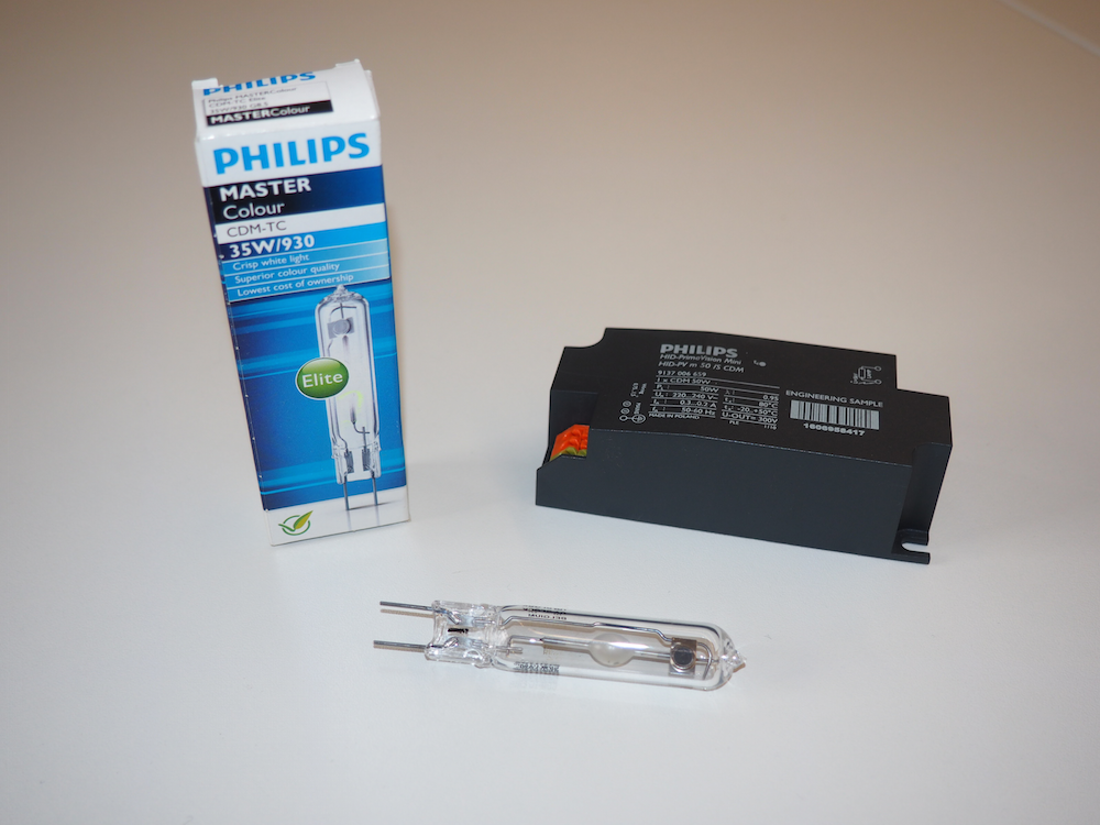

Left: MH lamps and corresponding driver. The simple fact that the driver is larger than the lamp itself indicates a certain imbalance. Ideally, the driver would be integrated into the lamp’s socket. Right: Design of an MH lamp. The arc tube filling consists of argon, mercury, and metal halides.
Addressing Instability in MH Lamps with Simulation
A True Multiphysics Model
To obtain an understanding of the processes inside the arc tube that lead to unstable lamp behavior, Thomas Dreeben considered a time-dependent 2D model in COMSOL Multiphysics (see theFurther Reading section). This model has the drawback of representing a lamp of infinite length. We opted to use a 3D model to get a more realistic description. The extra dimension requires additional computing resources, which cannot be handled even on powerful desktop systems. To compensate for this, a frequency domain model was used. The idea was to determine what physically happens at the frequency values during which the transition from stable to unstable behavior occurs.
This model is an excellent example of a multiphysics analysis. It comprises coupled differential equations for charge, mass, energy, and momentum conservation. On the basis of these equations, we computed the buoyancy-driven flow field and the temperature field in the interior as well as within the wall of the arc tube. The temperature field determines the space-dependent speed of sound, which is necessary for calculating the acoustic modes inside the arc tube and, based on this, the acoustic response (inhomogeneous Helmholtz equation). We then used the acoustic response to obtain the acoustic streaming flow field. Acoustic streaming (AS) is a nonlinear effect in which acoustic pressure oscillations drive a nonoscillatory net flow in the fluid. Consider this effect,illustrated here, to be the opposite of a flow field that generates noise.
Our approach does not allow for a coupling of the balance equations and the Helmholtz equation. To include the feedback of the acoustic streaming field on the temperature field, we adopted a recursion procedure that is described in the figure below. For the calculation of the flow field, we used the AS force obtained in the previous recursion step. Once a certain convergence criterion is met, this recursion loop is stopped.
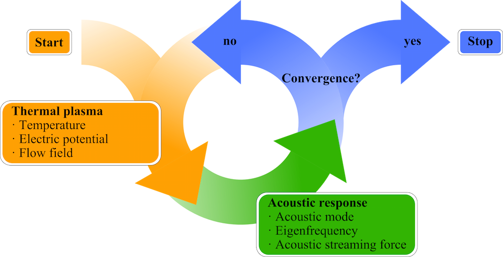
Recursion loop used to couple the AS and thermal plasma model.
Recapitulating the Forced Duffing Oscillator
The forced Duffing oscillator with a natural frequency of 1 is described by the following differential equation
whereyis the displacement,\zetais the damping ratio,Fis the force amplitude,\Omegais the angular excitation frequency, and\gammais the cubic stiffness parameter.
The only distinction to a harmonic oscillator is the nonlinear term\gamma y^3. If\gammais positive, the spring stiffens with increasing displacement (spring hardening). If\gammais negative, the spring becomes softer with increasing displacement (spring softening).
The oscillator is driven by a time-harmonic force, and the amplitude of the oscillation increases with the force amplitudeF. During one oscillation, the bob of the pendulum experiences the changing stiffness of the spring. In the case of a hardening spring, the averaged stiffness increases with the amplitude. Since the resonance frequency is related to the stiffness, it is also related to the amplitude of the oscillation. This contrasts with the linear oscillator (\gamma = 0) in which the resonance frequency is independent of the amplitude. The increase of the resonance frequency with the amplitude leads to the well-known tilting of the amplitude response curve toward higher frequencies. For a softening spring, the tilting is obviously toward lower frequencies.

Left: Response curves of a hardening spring for various damping ratios. Right: Response curve of a softening spring. The dashed portions represent an unstable solution. The frequency range\Omega_2 \leq \Omega \leq \Omega_1is called the region of bistability. If the frequency is increased starting from small values, the system jumps from the lower branch to the upper branch (point A). If the frequency is decreased starting from large values, the system jumps from the upper branch to the lower branch (point B).
An interesting effect connected to the tilting of the response curves is the jump phenomenon. When the driving angular frequency\Omegais increased starting from values well below 1 (the natural frequency), the amplitude of the oscillation is described by the lower branch of the amplitude response curve. Up to\Omega = \Omega_1, it behaves similar to a linear oscillator. At\Omega_1, the response curve of the Duffing oscillator has a vertical tangent, as shown in the above figure on the right. Here, the oscillator jumps to the upper branch of the response curve. Increasing\Omegafurther leads to a decrease in amplitude since the pendulum follows the upper branch. On the other hand, if the angular frequency is decreased starting from high values (\Omega > > 1), a jump to the lower branch occurs at the frequency\Omega_2. The system behaves differently during up-ramping and down-ramping of the frequency, and we see a hysteresis. For obvious reasons, the frequency domain between\Omega_2and\Omega_1is called theregion of bistability.
Comparing Experimental Data with Simulation Results
In our analysis, we concentrated on the acoustical mode shown below. It is the lowest-lying mode that is excited by the plasma arc, with an eigenfrequency of 47.8 kHz.
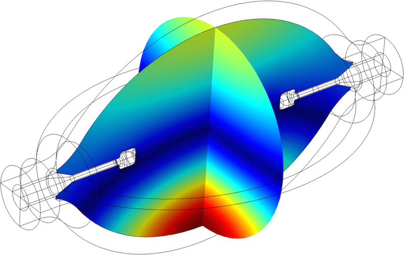
Acoustic mode in the arc tube. The absolute value of the acoustic pressure is depicted. Blue indicates the location of pressure nodes, while red represents the location of pressure antinodes.
The simulation began well below the eigenfrequency. Once the simulation converged, the AC frequency was slightly increased, and the recursion loop was started again. The solution from the previous step was used as an initial condition. This procedure was repeated up to the frequency at which the simulation ceased to converge. Additionally, the analogue procedure was carried out starting from a frequency well above the eigenfrequency, this time decreasing the frequency after convergence.
For each frequency, we recorded many important quantities such as the acoustic pressure, the temperature field, and the fluid velocity field. The voltage drop between the electrodes was of particular interest, as it can be easily compared to experimental results.
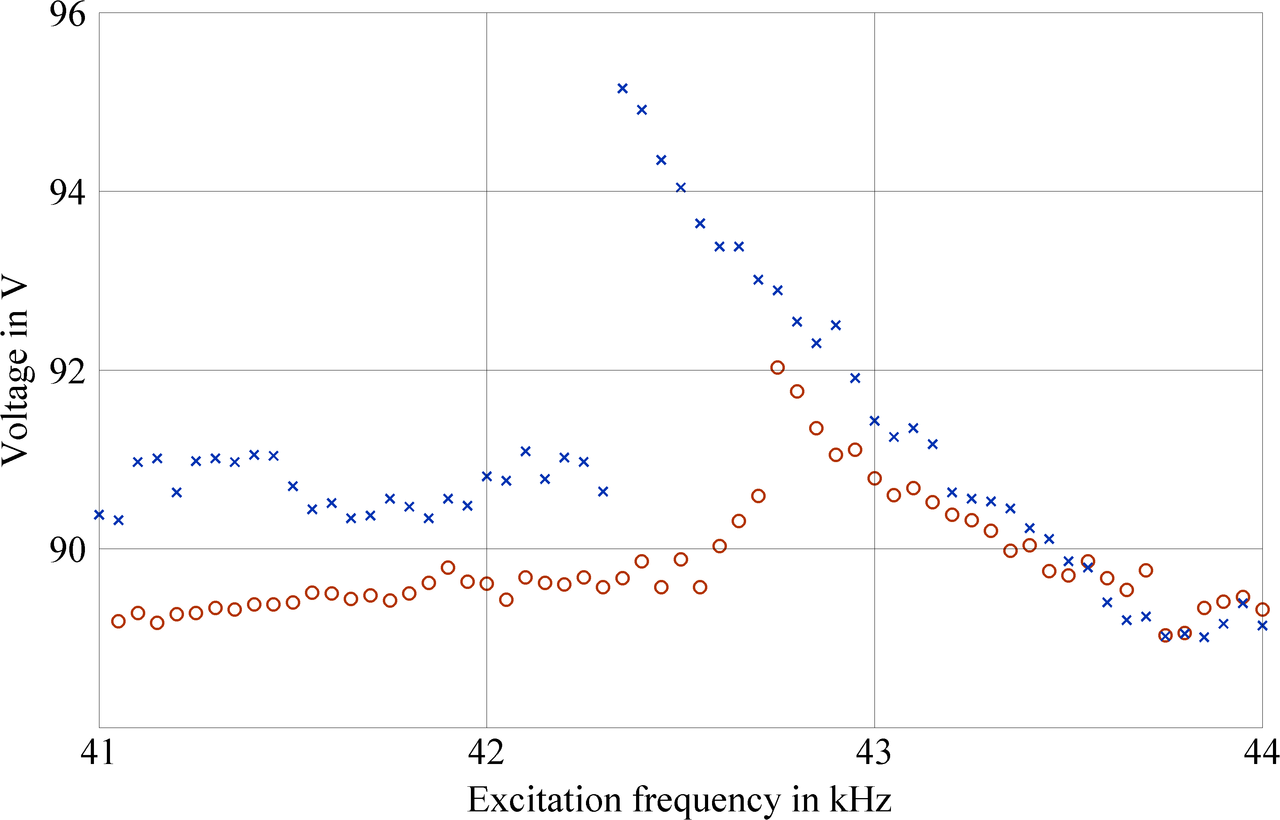
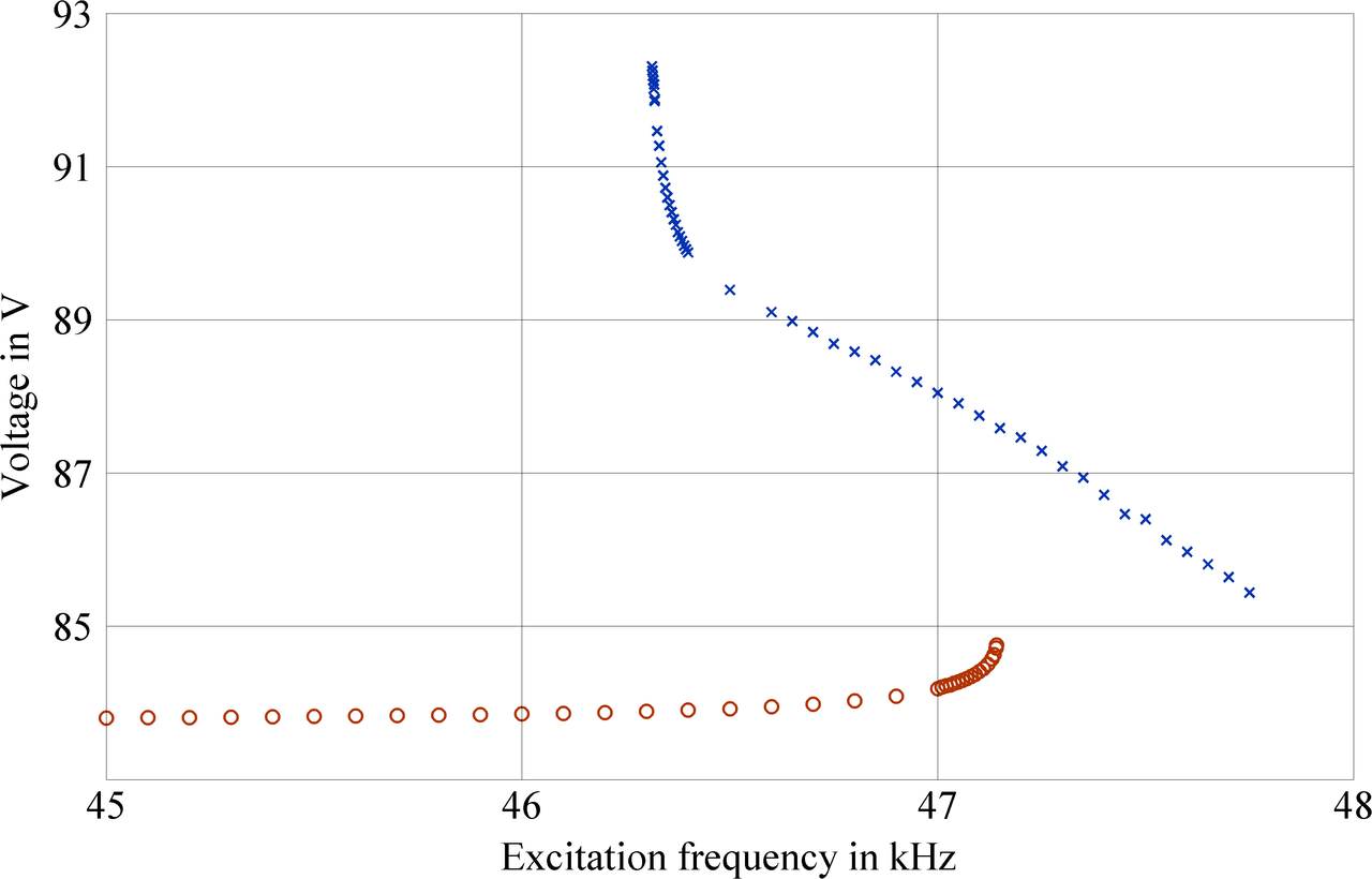
The accordance of the simulation results and the experimental data is quite satisfying. Both the experimentally measured voltage and the voltage resulting from the simulation analysis resemble the behavior of the Duffing oscillator with a softening spring, with the jump phenomenon and the associated hysteresis clearly visible. The measured voltage values are about 10% higher than the simulation results, and the region of bistability in the experiment is located at about 10% lower frequency values. This is not surprising, as there are uncertainties in the material properties and because of approximations in the finite element model. In the upper branch, the curve steepens before jumping to the lower branch, which we interpreted as saturation of the softening effect.
Left: Experimental results of the voltage for ascending (red) and descending (blue) frequency sweeps. The power input is a superposition of a low-frequency square wave and a high-frequency sinusoidal wave. Right: The corresponding results of the simulation. For obvious reasons, the unstable path of the response curve does not appear in these curves. The characteristic of a hysteresis is clearly visible.
The following figure shows the velocity field corresponding to the upper branch at the lower margin of the region of bistability. This simulation plot shows the characteristic of an AS force driven field. We can conclude this from the fact that the fluid flow in the lower part of the arc tube’s center is directed downward. For a flow field that is primarily driven by buoyancy, the flow in the center of the arc tube is pointing in the upward direction. For frequencies far off the jump frequency\Omega_2and everywhere on the lower branch, the flow field is mostly buoyancy-driven and considerably weaker.
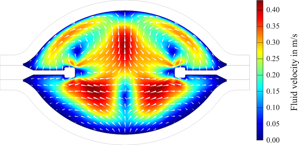
Flow field in the vertical center plane of the arc tube as it appears near the jump from the upper to the lower branch of the response curve (frequency of 46.313 kHz).
The strong AS flow, when the system is near the jumping-off point B, drags the hot plasma toward the lower part of the arc tube and, at the same time, pushes the hot plasma arc toward the upper wall. The plasma arc is thus stretched in the vertical direction and quenched in the horizontal direction. The resulting large temperature gradient near the upper wall leads to strong radiation losses and, theoretically, is accompanied by a drop of the mean temperature inside the arc tube. Calculations of the average plasma temperature near and far off the jump at point B confirm this. As such, we can conclude that the decrease of the mean plasma temperature is an important effect of a strong AS flow.
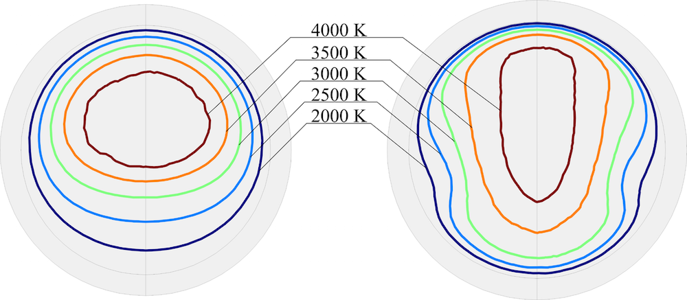
Isothermal lines in the vertical plane perpendicular to the arc tube’s axis. The left side of the image shows the lower branch of the response curve at 45.000 kHz. The right side shows the upper branch at 46.313 kHz (jump at point B), where acoustic streaming is strong.
Due to the temperature dependency of the electrical conductivity of the arc tube filling, this effect leads to an increase in the electrical resistance and the voltage drop between the electrodes, as the electric power is kept constant. The temperature drop also alters the speed of sound and thus the eigenfrequency. Just below\Omega_2, the eigenfrequency moves so far from its original value that the excitation frequency is off resonance and AS comes to a halt. Suddenly, the conditions inside the arc tube drastically change, with the system settling to the lower branch of the response curve. It seems plausible that the flickering of the light is related to the jump phenomenon.
Conclusions
Here, we have described how we set up a COMSOL Multiphysics model to simulate the processes inside the arc tube of MH lamps at high-frequency operation. Our model comprises electrical, thermal, and flow processes along with acoustics and acoustic streaming. The method we chose to calculate the acoustic pressure did not allow us to incorporate the coupling of all differential equations. Therefore, a recursion procedure was used to implement the coupling.
The voltage drop between the electrodes of the lamp as a function of the AC frequency was calculated and experimentally measured. When compared, the experimental results and our calculations were found to be in good accordance. Our results detected that the lamp’s system behaves similar to the well-known Duffing oscillator, in particular demonstrating the jump phenomenon and the corresponding hysteresis. It seems reasonable to assume that these effects are at the heart of the light flickering problem in HID lamps.
Joerg and I would like to thank the supporters of our research, the German Federal Ministry of Education and Research (BMBF) and Philips Lighting, as well as Mads J. Herring Jensen, a member of the COMSOL staff who provided us with assistance in addressing a pressure constraint issue.
Further Reading
- Read more about acoustic streaming and radiation forces in the COMSOLAcoustophoretic Force blog series
- Tamás Kalmár-Nagy and Balakumar Balachandran, “Forced harmonic vibration of a Duffing oscillator with linear viscous damping”, inThe Duffing Equation: Nonlinear Oscillators and Their Behaviour(2011), 139-173
- Thomas D. Dreeben, “Modelling of fluid-mechanical arc instability in pure-mercury HID lamps”, in the Journal of Physics D: Applied Physics (2008), 41(14):144023
- Bernd Baumann, Joerg Schwieger, Marcus Wolff, Freddy Manders, and Jos Suijker, “Numerical investigation of symmetry breaking and critical behavior of the acoustic streaming field in high-intensity discharge lamps”, in the Journal of Physics D: Applied Physics (2015), 48(25):255501
- Bernd Baumann, Joerg Schwieger, Marcus Wolff, Freddy Manders, and Jos Suijker, “Nonlinear Behavior in High-Intensity Discharge Lamps”, awaiting publishing
About the Contributors
Bernd Baumann received his master’s degree (Dipl.-Phys.) in physics and his PhD in theoretical physics from Hamburg University in Germany. From 1987 to 1992, he served as a research director in information engineering and, in 1992, he became a professor of physics at Hamburg University of Applied Sciences. In recent years, Baumann has focused on simulating and optimizing the signal strength of photoacoustic sensors and addressing the acoustic resonance problem in high-intensity discharge lamps. His additional research interests include the Monte Carlo simulation of random surfaces, stochastic optimization, and the application of the finite element method to field problems in physics.
Joerg Schwieger received his bachelor’s degree and master’s degree in mechanical engineering from Hamburg University of Applied Sciences. Since 2012, he has worked at the Heinrich Blasius Institute for Physical Technologies at Hamburg University of Applied Sciences, where he is currently a doctoral candidate. In recent years, Schwieger has used simulation-based research and experiments to analyze the acoustic resonance phenomenon in high-intensity discharge lamps. Some of his other research interests include performing numerical simulations and optimizations as well as addressing multiphysics problems and acoustical phenomena.




Comments (0)