
Today we welcome guest blogger René Christensen from Dynaudio A/S.
When evaluating loudspeaker performance, dips and/or peaks in the on-axis sound pressure level can be a result of an unfortunate distribution of phase components. To overcome this, we use a phase decomposition technique that splits a total surface vibration into three components depending on how they contribute to the sound pressure in an arbitrary observation point; either adding to, subtracting from, or not contributing to the pressure.
Loudspeaker Vibration and Sound Generation
A commonly used metric in loudspeaker performance is the sound pressure level as a function of frequency in an on-axis observation point. If at some frequency the overall displacement is decreased compared to adjacent frequencies, the resulting sound pressure level will have a corresponding dip at that frequency. However, the converse is not necessarily true. In other words, a dip in sound pressure may not always be a result of the overall displacement being low; rather, it may so be that part of the vibrating surface contributes negatively to the resulting sound pressure level.
Introduction to Phase Decomposition
By applying phase decomposition to the vibration, the underlying nature of the vibration can be exposed. The decomposition splits the total displacement into three parts, each of which either adds to, subtracts from, or has no influence on the sound pressure in an observation point of choice. The technique is available in at least one software package, but here the intended input is measured data from a laser vibrometer and not simulated vibrations.
Third-party software is available to enable the use of exported displacement data from COMSOL Multiphysics as input for the scanning software, but here I will show you how the entire analysis can instead be carried out using only COMSOL Multiphysics and the Acoustics Module.
The Rayleigh Integral for Pressure Evaluation
As a starting point, we assume that the vibrating surface is flat and placed in an infinitely large baffle. Since only the normal displacement contributes to the sound generation, we align the surface normal \mathbf{n} with the z-axis, and denote this displacement phasor \mathbf{w}. This is in accordance with the COMSOL Multiphysics convention.
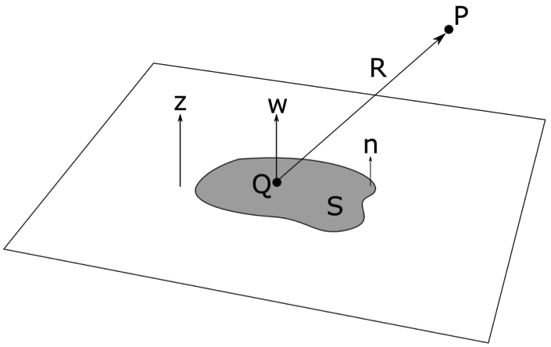
The flat radiation surface area shown in gray is assumed to be placed in an infinite baffle.
For this situation, of a flat vibrating surface, the sound pressure level can be calculated via the so-called Rayleigh integral (see any standard acoustics text book, for a more advanced text on the subject see, for example, Fourier Acoustics, by E. G. Williams):
Here, \pmb{p}(P) is the pressure phasor in observation point P, \omega is the angular frequency, \rho is the density of the fluid medium, \mathbf{w}(Q) is the displacement phasor in point Q on the vibration surface area S, k is the wave number, and R is the distance from a point Q on the radiating surface to the observation point P.
If air loading is low, that is, the forces exerted on the vibrating surface by the fluid are small enough that their effect on the surface vibration is negligible, there is no need to include an acoustic domain. In that case, the sound pressure can be determined from a purely structural simulation.
Phasor Projections
Assuming that the geometry in question is flat enough for the Rayleigh integral approach to be acceptable, the surface vibration can be split into three components:
- In-phase component, which contributes positively to the sound pressure
- Anti-phase component, which contributes negatively to the sound pressure
- Quadrature, or out-of-phase, component, which neither adds to nor subtracts from the sound pressure in the chosen observation point
The phase components can be determined by looking at a phasor diagram relating the phase of the total displacement in a point Q on the vibrating surface to the phase of the pressure in the observation point P.
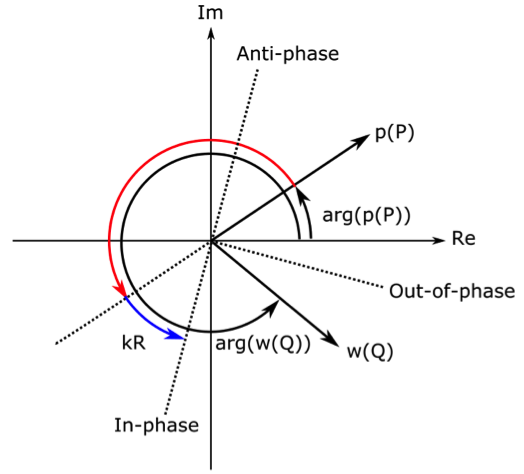
The phasor relationship between the displacement in a point Q and the pressure in observation point P.
Since the pressure here is found via the Rayleigh integral, the sign difference between the displacement and the pressure is first accounted for by a phase shift of π radians, indicated by the red arrow. Now, consider what an in-phase displacement component means: The phase of the in-phase displacement component should lead the phase of the pressure by a phase shift exactly matching the distance traveled by the sound wave from the local point on the surface to the observation point. This phase difference of kR is indicated by the blue arrow.
The phase of the displacement \arg(\mathbf{w}(Q)) is shown for a situation where it is not aligned with the in-phase axis. By projecting \mathbf{w}(Q) onto the in-phase axis, we can determine its in-phase component. We can find the out-of-phase and anti-phase projections in a similar way; the former being in quadrature with the in-phase component and the latter being π radians offset to the in-phase component. By visual inspection, we can observe that there will be a nonzero out-of-phase projection, which is larger than the in-phase projection, but no anti-phase component for the surface point and observation point in question.
The analysis is carried out over the entire surface in order to obtain the three vibration components. Each component can subsequently be fed back into the Rayleigh integral to calculate its respective sound pressure component. By definition, the out-of-phase surface vibration naturally does not have a corresponding sound pressure contribution. This displacement simply cancels out acoustically in the observation point in question.
Let’s review a couple of simulation examples: one of a vibrating disk and another of a loudspeaker.
Vibrating Disk Example
First, we will illustrate the phase decomposition technique with a vibrating disk as a test case, where the individual phase components can be found by visual inspection.
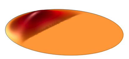
We’ve chosen an on-axis observation point several radii away from the disk. Let’s consider the total plate vibration shown in one of the four figures below. A larger part of the vibration has one particular phase, whereas a smaller part of the plate has an opposite phase. The larger part of the displacement must be in-phase for an on-axis observation point. This can be realized by considering the “extreme” case that the entire vibration has only one phase. Such a vibration must contribute entirely positively to the sound pressure in an observation point on-axis and away from the plate surface.
We’ve applied the phase decomposition technique to the total displacement and found the expected in-phase component. Since the remaining displacement is in opposite phase of the in-phase component, it must then be an anti-phase component. The analysis in COMSOL Multiphysics confirms this.
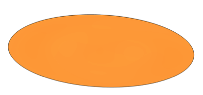
Lastly, since the total displacement is made up entirely of an in-phase and an anti-phase component, the out-of-phase component must be zero. This is also what we find via the phase decomposition.
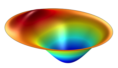
Total
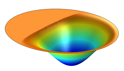
In-phase
Anti-phase
Out-of-phase
Displacement components of the vibrating disk for an on-axis observation point.
Note that if we choose another observation point — for example, off-axis and/or very close to the plate — we will get different displacement components than those shown above for the same total displacement.
Loudspeaker Example
Next, we use the phase decomposition technique for a 3-inch driver placed in a baffle. We carried out a complete 2D axisymmetric vibroacoustic simulation for a wide frequency range. The electromagnetic system was included in a lumped fashion, so that an input voltage could be applied directly.
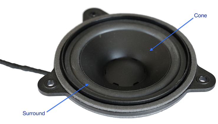
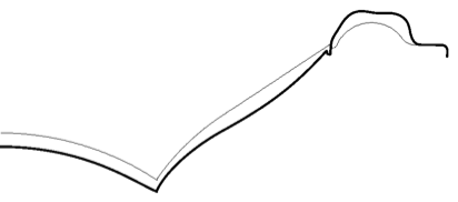
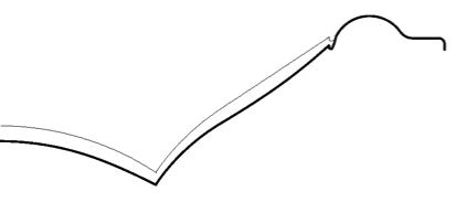
The surface displacement components are illustrated for a frequency of 4.5 kHz. The total displacement pattern seems fairly simple, but visual inspection cannot reveal the individual phase components.
Total
In-phase
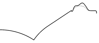
Anti-phase
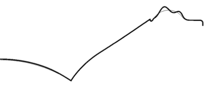
Out-of-phase
Displacement components of the loudspeaker surface at 4.5 kHz for an on-axis observation point.
Just as with the previous example, we chose an observation point on-axis and several radii away from the surface. The in-phase component is concentrated around the inner topology, or the cone, whereas there is no in-phase displacement at the outer part of the surface, the so-called surround. The anti-phase component is concentrated around the surround part of the surface.
This means that the surround is the part to investigate (material and/or topology) if the anti-phase displacement is found to be unacceptably large. The surround is also the sole contributor to the out-of-phase displacement at this particular frequency.
I should note that the phase-decomposed displacement components have no radial components, since the analysis assumes a flat vibrating surface. Therefore, they do not sum exactly to the total vibration for this case, since the total vibration has both axial and radial components. However, the analysis still provides insight into the vibration pattern and how the individual components affect the resulting sound pressure in the chosen observation point.
By feeding the displacement components back into the Rayleigh integral, we can find the individual pressure contributions.
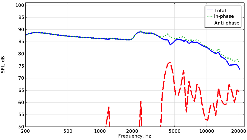
The sound pressure level components for the loudspeaker driver.
We can see that at low frequencies, the total displacement is dominated by in-phase motion, but above approximately 4 kHz, the anti-phase component subtracts from the pressure. The insight provided by the phase decomposition technique can aid engineering decisions and, in some cases, design changes may be warranted.
Concluding Thoughts
The phase decomposition technique is, of course, not limited to loudspeaker analysis. Any vibrating structure that is fairly flat can be analyzed. In fact, it’s advantageous to apply the Rayleigh integral on its own in order to have an estimate of the radiated sound without having to include an acoustic domain, especially if the air loading on the vibrating surface is negligible. The phase decomposition can then be added as a further layer in the analysis.
Special thanks to Mads Herring Jensen, the technical product manager for the Acoustics Module at COMSOL A/S, for help with the implementation.
About the Guest Author
René Christensen has been working with vibroacoustics for about a decade for a handful of companies such as DELTA, Oticon A/S, and iCapture ApS. He holds a PhD in hearing aid acoustics with focus on viscothermal effects. René recently joined the R&D department at the Danish loudspeaker company Dynaudio A/S where his main responsibilities are development and optimization of drivers for the “Automotive” and “Home” lines, design of waveguides and cabinets, and conceptual work for future products.


Comments (0)