
Last week you saw how you can simulate theheating of a car’s brake discs. This reminded me of another type of brake — the eddy current brake (also known as magnetic brake). Whereas the other model was a study in heat transfer, eddy current brakes deal with electromagnetics.
Basic Structure of Eddy Current Brakes
Eddy current brakes basically consist of a rotating disc (made of conductive material) and a permanent magnet:
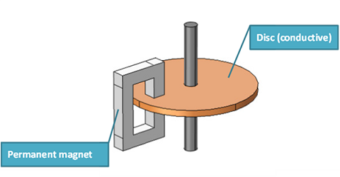
As the disc spins in the constant magnetic field generated by the permanent magnet, its conductive properties induce eddy currents. The Lorentz forces from these currents in turn slow down the disc. The most common application areas of magnetic brakes are trains, roller coasters, and aircraft. It’s not unlikely that eddy current brakes will eventually befound in cars as well.
You may have also heard of electromagnetic brakes, which are similar in design, except instead of a permanent magnet they have iron wound with a coil.
Modeling Eddy Current Brakes
Let’s suppose you are designing an eddy current brake, and you want to know how large the permanent magnet needs to be in order to provide enough torque to slow down the vehicle (train, roller coaster, car…) in time. In this case we’re assuming the induced current distribution does not move with the rotating disc; it stays where the magnet is located.
Note that the induced Lorentz current density term often leads to confusion when modeling electromagnetics where there are moving magnetic sources or the moving domain is of bounded extent in the same direction as the motion or varies in this direction. These types of moving sources generate magnetic flux that cannot be included in the Lorentz term. To be clear, in our case the induced current distribution is stationary and does not move with the disc.
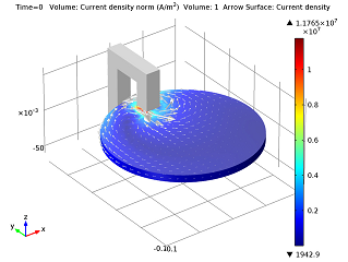
Let’s assume you have a copper disc that’s 1 cm thick, has a radius of 10 cm, and moves at an initial angular speed of 1,000 rpm. The 1 T permanent magnet is connected via an iron yoke, and there’s a 1.5 cm gap of air where the disc can spin. Using COMSOL Multiphysics and theAC/DC Module, you can figure out how much torque your brake system will have. What’s notable is that you can include the rotation of the device without having a moving mesh. Themagnetic brake modelcouples a dynamic equation (this defines the rotation of the disc) with thefinite element method(this defines the torque). This will allow you to calculate the total time to completely brake the system.
 |
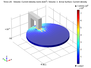 |
| 3D model showing induced eddy current density and direction at t=0 s. | 3D model showing induced eddy current density and direction at t=25 s. |
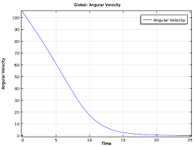
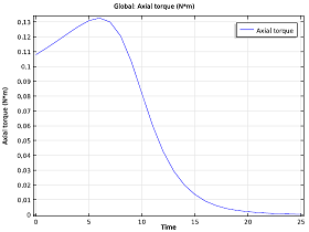
You can also plot the time evolution of the angular velocity, braking torque, and dissipated power in your magnetic brake system:
 |
 |
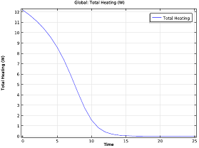 |
| Time evolution of the angular velocity. | Time evolution of the braking torque. | Time evolution of the dissipated power. |


Comments (3)
LIM JUJOE
June 6, 2020Hi, I have faced a problem when I change the disc material into low carbon steel with error NaN or Inf found when solving a linear system using SOR. But, it runs! if I change to other materials. Any comments or advice? Appreciate if your response.
Fanny Griesmer
June 8, 2020 COMSOL EmployeeHello Lim,
Hmm that’s interesting. Our Support team should be able to help you out with that. You can contact them viasupport@comsol.comor//www.denkrieger.com/support
In the meantime, there’s another post about eddy currents that you might find interesting://www.denkrieger.com/blogs/how-eddy-current-braking-technology-is-freeing-us-from-friction/Good luck!
Avishek Chowdhury
May 7, 2021Hi, I am working on a electromagnetic braking system. Since it works based on the eddy current principle does the simulation process same as above? Waiting for your kind suggestion.