Optical fibers are used to transmit information in the form of light through an optical waveguide made of glass fibers. The light is sent in a series of pulses that can be translated as binary code, allowing the transfer of information through the fiber. Because such pulses can travel with less attenuation and are immune to electromagnetic disturbances, fibers are used instead of traditional metallic wires thus allowing data transmission over longer distances and at higher bandwidths.
What is a Step-Index Fiber?
A step-index fiber is an optical fiber that exhibits astep-index profile; the refractive index remains constant throughout the core of the fiber, while there is an abrupt decrease in the refractive index at the interface between the core and the outer covering, or “cladding”. The step-index profile can be used for both single-mode and multi-mode fibers.
Single-Mode vs. Multi-Mode Waveguides
Single-mode fibers have smaller cores (about 10 microns in diameter) than multi-mode fibers and the difference between them lies mainly in themodal dispersionthey exhibit and the number of different modes that can be transmitted. Single-mode fibers have a narrower modal dispersion, which means that they transmit each light pulse over longer distances with better fidelity than multi-mode fibers. This is why single-mode fibers, for example,exhibit a higher bandwidththan multi-mode fibers.
Analyzing a Single-Mode Step-Index Fiber
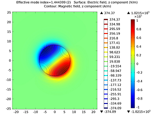
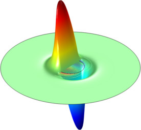
Below you can see a simulation of astep-index fiberwhere the inner core is made of pure silica glass (SiO2) and has a refractive index of 1.445. The cladding has a refractive index of 1.4378. For the simulation results shown below, a mode analysis is made on the xy-plane of the fiber, where the wave propagates in the z-direction. A lot of information can be deduced from this type of eigenvalue, or eigenmode, analysis of just a cross-section of a fiber. Due to the symmetry of the fiber cross-section, the lowest eigenmode is degenerate and light sent into the fiber will propagate at the same speed for both of these modes of propagation. What happens if we squeeze the fiber hard or if there were manufacturing errors? It may then happen that the glass becomes birefringent with different refractive indices in different directions. The lowest eigenmode will then split and not be degenerate anymore: light will propagate at a different speed for each mode resulting in dispersion of the signal. This is just a very basic example; real-world analysis scenarios can of course be much more complicated.
 |
 |
| The surface plot and contour lines visualize the z-component of the electric field and the magnetic field, respectively. | Alternative visualization of the plot on the left where a height expression based on the electric field value has been applied to the surface plot. |
Revolutionizing Communication with Fiber Optics
Although the concept behind fiber optic communications has been around since the 1800’s, it wasn’t until recently that they were implemented in the modern world. Light is transmitted through the fiber using a principle calledtotal internal reflection, which allows the light to be propagated down the waveguide with (theoretically) zero loss to the outside environment. However, since we don’t live in a theoretical world, information losses do occur. Prior to the 1970’s, optical fibers were prone to large transmission losses, making them purely an academic endeavor. However, in 1970, researchers were able to show that it was possible to manufacture low-loss optical fibers. These new waveguides demonstrated losses as low as 20 decibels per kilometer (dB/km), instead of the 2,000 dB/km that were shown in previous experiments. Thanks to years of intensive development, today’s fibers have losses that are near the theoretical limit for a given combination of materials used and geometrical characteristics.
Between 1990 and 2000, the commercial optics market exploded, with cables implemented worldwide in just a few years. As Thomas Allen wrote in hisNational Geographicarticle “The Future is Calling” in 2001, “It took a hundred years to connect a billion people by wire. It has taken only ten years to connect the next billion people.” Fiber optics revolutionized communication in the 1990’s and today, and improvements in transmission efficiency and cost of production continue to bring faster and more efficient communication to the developed world.
Other Fiber Optics Applications
While the most widespread use of fiber optic cables is in communication technologies, there are also many other applications that have been revolutionized through the use of optical waveguides. For example, in the medical field, physicians use optical fibers tolook inside a patient’s body during surgery or exploration. Fiber optics allow physicians to conduct minimally invasive surgeries using tiny incisions and endoscopes to provide light. They are also used in scientific research and manufacturing to provide light to hard-to-reach or hazardous areas. Fiber optic cables can also be used as sensors within machines or vacuum chambers, providing information about pressure, temperature, or voltage changes. What other types of applications do you think optical waveguides could revolutionize?
Analysis of Optical Components
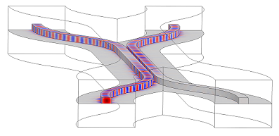
Optical fibers are not the only optics component that can be analyzed. So-calledphotonic devicesin future optoelectronic circuits pose challenges for simulation software, typically because of their elongated shapes that imply plenty of electromagnetic wave oscillations in the direction of propagation. Also, 2D simulations won’t do — you need a full 3D simulation. Each oscillation in the direction of propagation needs to be densely sampled regardless of the numerical method used in order to achieve the necessary accuracy. A soon-to-come blog post will describe some new and exciting technologies that we at COMSOL are working on to make this easier. The picture below of adirectional splitteris a great example of such a challenging photonics component:

Further Reading
- Model Download:Step-Index Fiber
- Model Download:Stress-Optical Effects — with Generalized Plane Strain and in a Photonic Waveguide
- User Story:COMSOL simulates processors for fiber optics communication


Comments (0)