Hi. I'm trying to simulate the current or rather the E. Field produced inside a conductor of a certain shape and size. The conductor will be placed in an External E. Field produced by a charged spherical shell placed at a certain distance away from it. I'm clueless on how to proceed with this. So, can somebody help me get through it ?
Hello,
I am trying to accurtely model electrohydrodynamic conduction pumping in 2D in COMSOL. I have had good success with modeling this when I assume the surface charge density on the substrate layer is set to zero. The substrate layer is the non-conducting material between adjacent conducting electrodes, and is typically electrically insulative. Please note that all other aspects of the model are working correctly (laminar flow, ionic species transport, phase-field, etc.).
In literature, a more accurate electrostatic boundary condition is as follows:
n・∇ɸ = ?_s /?
where ɸ is the potential, ?_s is the surface charge, and ? is the absolute permittivity of the working fluid. This essentially says that the normal dotted with the gradient of potential, is equal to the surface charge over the permittivity. I can solve for values for surface charge and I know the permittivity and applied voltage.
My issue arises in implementing this boundary condition on the substrate in COMSOL under the electrostatics module. I cannot find any built in boundary condition that would accomplish this, nor do I know how to implement this onto the substrate as a custom boundary condition. I tried to write it as an analytical function in the definitions tab at the start of the model, but I am struggling to correctly do this as well.
Any guidance on this would be extremely helpful! Thank you! A screenshot of my electrostatics section of my model is attached.
Hello, I would like to know how to access the number of nodes in a COMSOL mesh? Thanks for your help
Hi all,
I am a new comsol user, and am getting started with a very simple solid mechanics modeling problem. Here is the basic setup:
- Rotationally symmetric steel shell with 1.0 m and 0.5 m outer and inner radii respectively. The Young's modulus is 200 GPa, and the Poisson ratio is 0.3.
- The boundary load on the outside boundary is P_1 = 10 Pa.
- The boundary load on the inside boundary is P_2 = 1 Pa.
- Solve for the equilibrium stress tensor and displacements.
I am attaching the .mph file for this problem. This particular problem is analytically solvable. For such a small pressure difference, the displacement of the outer boundary should be tiny. When I solve, I see this is actually the case. One of the attached plots is the calculated displacement along the radial direction. The reported displacement is negligible.
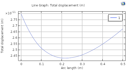
However, when I display the 2D and 3D models of the stress, it looks like the whole model has been compressed by 20 cm in the radial direction (see attached figure). When I set P_1 = P_2 = 0, there is no compression (but also no stress field), however any nonzero pressure difference is giving me these crazy nonphysical distortions of the body.
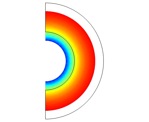
What am I doing wrong here!
Hi, I have a frequency domain study, and I would like to export a given plot (surface field at a waveguide port) for each of the frequencies in an automatic way. How can I do it?
Hello, i m trying to model a plate where I attach some particle dampers modelled as a equivalent nonlinear viscous damping coefficient(Ceq) and a mass(Md). (lumped damper and mass).(see picture) The problem is that the equivalent nonlinear viscous damping coefficient depend on: levels of excitation (frequency ) ,the excitation velocity amplitude and the second invariant deviatoric stress. My question is: 1 how can i add Md and Ceq to the equation of motion Ma+Ks+Cv=F? My idea is using lumped mass-spring-damper physics but since Ceq is a big and complex equation depending on the above parameters should i instead PDE module (weak form ). 2) should i first study the plate without the damper and use the excitation velocity amplitude and the second invariant deviatoric stress result to add them to the full system? PS: i have solid mechanical structure physics coupled with pressure acoustic(frequency ).
i want to study the pressure attenuation in the air of the vibration of plate in frequency domain due to a point load.
I attach scheme of the plate plus dampers and equation that i have to implement. thanks in advanced
This will be useful among collaborators. What if .mph created of a high comsol version is saved as .m then .m is opened in a low comsol version, should that work well? Is this the go to method?
I am testing a simulation involving a rectangular waveguide coupled to a cylindrical cavity. The goal is to analyze how varying the port power from 0 to 1 kW every second affects the system. For this, I am running a transient simulation where the port power oscillates between these values every second.
Initially, I attempted to implement this by creating an analytical function that fluctuates between 0 and 1 each second. I then multiplied the port power by this function within the simulation. However, the simulation resulted in an error and did not run at all.
If anyone has experience with similar simulations or has successfully managed transient simulations with oscillating power inputs, I would greatly appreciate any insights or recommendations. I am particularly interested in tutorials or resources that might help resolve this issue and improve our simulation approach.
Please feel free to share your suggestions or direct me to relevant tutorials that could help address this problem.
Hello, I m trying to couple the vibration of a plate due to an harmonic force, and the propagation in the air domain. basically i want to study spl in the air domain due to vibration. Could you have any suggestion how to do it in terms of step? I need both time domain and frequency domain. I have use acoustic-structure multiphysics. I have followed the tutorial gear noise but it doesn't work. I try to set as boundary condition in the pressure acoustic, frequency domain normal acceleration from solid mechanisms but i do not know how to implement it (using also general extrusion to couple the domains but it s not working). I also plot the eigenmode of plate plus air and they look completely wrong any ideas?. Thanks in advance.
When simulating an optical system using COMSOL, the heating effect of the laser on the device needs to be considered due to the large laser power. However, the Wave Optics Module of COMSOL is computationally intensive and complex for calculating the optical-mechanical-thermal effects of complex optical systems, so the use of ray optics to trace the laser propagation is considered for simulation. The Gaussian beam is used for the experiment, and the correlation simulation of the Gaussian beam by COMSOL is mainly found in the Wave Optics Module, so I asked how to use the Ray Optics Module to construct a Gaussian light source and model the propagation of Gaussian beams in the optical system?
Hello,
I have designed a CAD model of 3-Phase Bldc motor and bearing assembly. The parts are connected in this way,
Motor's Shaft to one end of coupling, a stepped shaft to the other end of the coupling, bearing inner race to the stepped shaft and outer race of the bearing is fixed.
motor shaft + coupling + stepped shaft + bearing
i have used solid mechanics physics and applied it to the domains stator core, rotor, shaft, coupling, stepped shaft and whole bearing.
while defining contacts between parts i have selected augmented lagrangian and fully coupled formulation.
used magnetics and electric currents physics to define coil currents and other boundary conditions to the domains stator, windings, rotor, magnets.
Assigned materials to every component and used a fine mesh to entire geometry.
i have selected a time dependent study but it is taking so long to compute for a time range (0,0.1,1)
Is there any other way to reduce the computation time or am i did any mistake in physics selection or anywhere else.
Thanks for your time. If anyone know how to deal with this, kindly share your thoughts.
Hi,
I am relatively new to comsol and have been attempting to fill a large microfluidic well. The simulation is in 2D, with a rectangular channel of length 1 mm and width 0.1 mm feeding into a well of radius 2.3 mm, where an outlet channel is then connected to the end of the well (same dimensions as the inlet channel. I have been able to successfully simulate this structure on a smaller radius well, but have been experiencing a lot of trouble in terms of getting viable results for the larger radius well. The most success I usually have is with a mapped mesh. I am unable to attach the file at the moment, but will do so in the coming hours. If anyone has any experience doing such a simulation, your insight would be extremely helpful, thank you!
I'm modeling inductive heating by a coil. In the model, a tantalum sample is placed in a graphite crucible. Some of the tantalum surfaces are opposite to those of the graphite crucible. Since the tantalum is hotter (1900K) than the graphite (1300K), I expect temperature gradients in the graphite, but calculations show an almost constant temperature.
A warning is displayed : Boundaries for which only the opposite side has well-defined material properties can be seen from a point computing the irradiation. This may be due to erroneous definition of the boundary radiation directions or the opacity of the adjacent domains. comp1.rad.Fbacksideu can be plotted to show the faces that see the opposite side of other boundaries.
This is not clear for me, the radiation directions seem to be OK. The heated pieces are under vacuum so I set the adjacent domain as "transparent"
Can anyone help me on this point ?
Thanks in advance
Hello COMSOL Community,
In the typical segregated approach, it’s possible to limit a variable between an upper and lower bound. In the case of, the phase field variable needs to remain between 0 and 1. However, when using the monolithic or fully coupled solver, I haven’t found a way to enforce these limits.
My question is: How can I ensure that the phase field variable stays within the range of 0 to 1 when calculating energy, which depends on this variable, while using the monolithic solver?
I would appreciate any insights or suggestions on how to approach this issue.
Thank you!
Dear,
I have performed a calculation for a convection problem using COMSOL's General Form Equation.
The problem arises when I want to introduce a Flux/Source type condition. The software gives me this error:
The d-operator is not well defined in the current context, use dtang or mean and d operators instead
I make the change to the indicated function but it keeps giving me an error and I have to change to a Dirichlet type condition, which is not the most correct for this problem. With this condition I try to calculate d(P,x) at a point at the end of the domain and I get the same error. And I can't solve it with the function change that COMSOL indicates.
It should be something easy to solve, in the end it is just a matter of calculating a derivative or imposing a derivative. I attach the file in case you want to take a look at the model.
Could you help me with this?
Thank you all very much.
Best, Andres
Dear sir,
In my model i have done one analysis , the initial values of temperature is given as 300K but when the software plots the graphs it started from 0K all the graph pattern is ok but intial temperature is not seen
Hello,
I'm receiving the attached error when I try to save my COMSOL 5.3a project. Any advice on how to proceed? I am able to run my model fine, but whenever I attempt to save I get this error. I have cleared the solutions for all studies but that hasn't fixed anything.
Hi folks, I am trying to model displacement of PMUT array. Structure of model includes Sillicon on insulator wafer (SOI), Pt bottom electrode, 1.5um thick piezoelectric material (PZT-8) layer and top electrode. Part of SOI substrate removed (trenches etched from the bottom part to release PMUT elements). Thin layer of Si left below PZT. (akka unimorph with fixed edges). I have experimental data showing increased deflection within released part of PMUT (Etched trench has long oval shape, displacement pattern looks like half of ellipsoid). I created model in Comsol. Applied +5V to top electrode and ground to bottom electrode. Used this example as a reference: https://www.comsol.com/paper/modeling-and-analysis-of-thermal-bimorph-using-comsol-multiphysics-15585
I applied fixed constrained to entire substrate body, in this case displacement pattern look uniform and very small. I also tried to ally fixed constraint to outer boundary of substrate. in this case I see huge deformation of substrate that I don't see on experiment. Here is my model: https://drive.google.com/file/d/1hVWu5MwrB_JuRiNUaEuc152skwUdYRWK/view?usp=sharing
Could you please help with defining proper boundary conditions?
Thank you very much!
Stanislav
I am resuming a study that I carried out a few years ago. I slightly modified its geometry and added a few elements. When I restart the calculation, some elements that I added seem not to be taken into account in the calculation. In particular I have no temperature value. I don't know if the problem is with the geometry definition, the solver or the display. I can't figure out what the problem is. I've restarted a new study from scratch but it did not solve the problem. Can anyone help me? Thanks in advance.
Dear All,
I have conducted a prestressed eigenfrequency study on a structure using two steps:
1. Step 1: A stationary analysis with thermal expansion (+15°C) and tensile load.
2. Step 2: An eigenfrequency analysis using the results of Step 1 as the initial conditions.
In this study, the eigenfrequency values are determined under the conditions of the structure being heated and subjected to load.
Now, I would like to perform an eigenfrequency analysis at a cooled temperature, i.e., at room temperature, while considering the deformed shape and residual stress from the heated state (not the initial state prior to heating and loading). My goal is to simulate the behavior of the structure in the context of Shape Memory Polymers (SMP) processes.
Does anyone have experience dealing with this type of analysis? Your assistance would be greatly appreciated.
Thank you very much for your help!
Prestressed eigenfrequency study is described here: https://www.comsol.com/forum/thread/342041/how-to-use-stress-and-displacement-results-from-1st-stationary-simulation-as-ini