Geometry Concepts and Nomenclature in COMSOL Multiphysics®
Whether you are building a geometry natively in COMSOL Multiphysics®, using a LiveLink™ product, or importing CAD or mesh data from an external program, it is important to know how your geometry is organized within the software. This is so that you can properly apply settings to your model geometry. It is also important to know the terminology used in COMSOL Multiphysics®, such as whatdomainsandboundariesare. In this article, we will review these naming conventions that you will encounter when building geometry or assigning settings to a model geometry.
How the Geometry Is Organized
The terminology used in COMSOL Multiphysics®for the various parts of a model geometry varies between the geometry creation stage, the geometry sequence, and the physics modeling stage, as well as everything that comes after. In the physics modeling stage (for example, when assigning material properties, mesh settings, and physics definitions), there are certain terms we use to refer to geometry in the software. They consist of the following:
- Geometric objects
- Geometric entities
- Domains
- Boundaries
- Edges (3D geometries only)
- Points
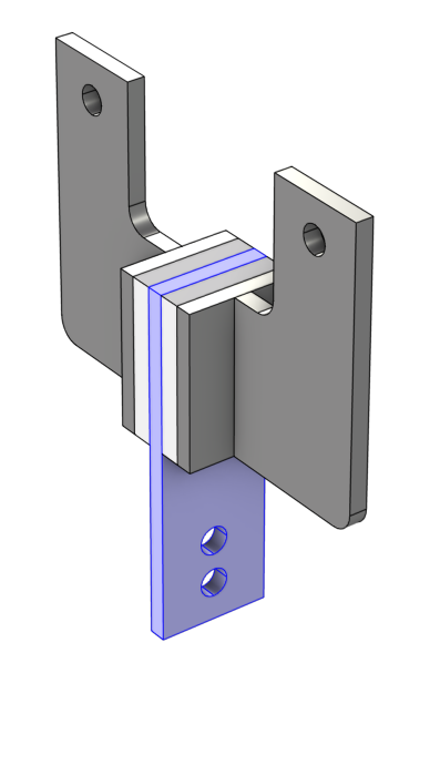
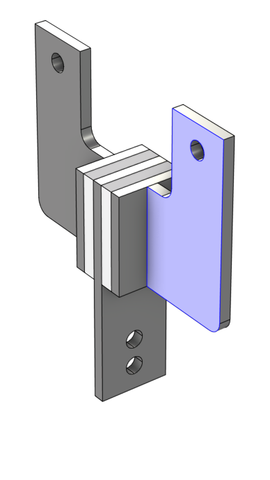
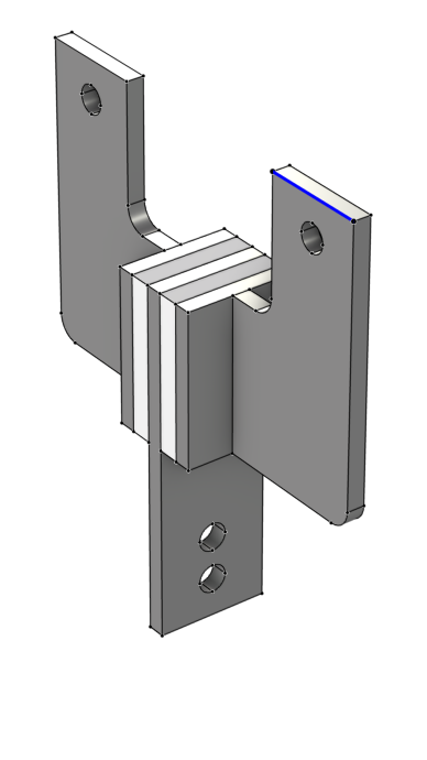
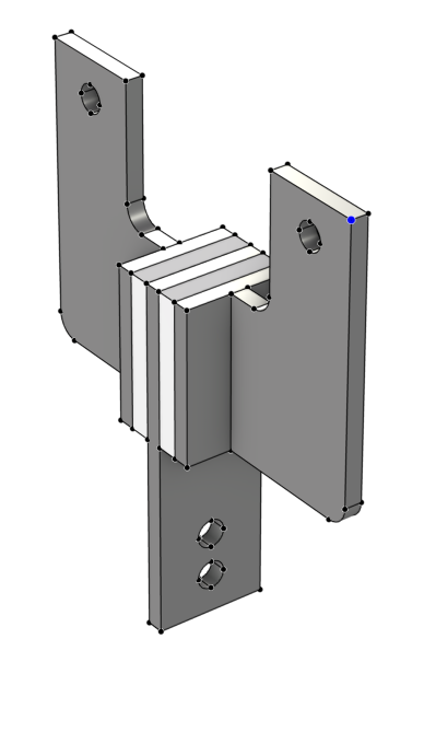
For a 3D geometry, the terminology that is most commonly used is that a volume enclosed by surfaces forms asolid, an area enclosed by edges forms asurface, and a curve enclosed by points forms acurveorline. The COMSOL terminology for geometry similarly follows this: For a 3D geometry, a solid volume enclosed by surfaces forms adomain, a surface area enclosed by edges forms aboundary, and a curve enclosed bypointsforms anedge. This is visualized in the table below for clarity, using an example of a viscoelastic damper. The generally used terms along with the appropriate COMSOL naming convention for the part of geometry highlighted in blue is outlined:
 |
 |
 |
 |
|---|---|---|---|
| Solid (Volume) | Surface (Area) | Curve (Length) | Vertex |
| Domain | Boundary | Edge | Point |
Note that when performing the geometry modeling step in COMSOL Multiphysics®, boundaries in 3D are also referred to asfacesand points are also referred to asvertices.
When setting up the physics in COMSOL Multiphysics®, domains, boundaries, edges, and points are referred to asgeometric entities; and ageometric objectis a collection of geometric entities. These concepts are explained further in subsequent sections.
Geometric Objects
A geometric object can be of the type solid, surface (3D only), curve, point, or mixed (a mixture of two or more types) and contains entities such as domains, boundaries, edges, and points. However, only a solid object can contain domains. A surface object, even if the surfaces form a watertight region, does not contain any domains, but can be formed into a solid object using geometry operations.
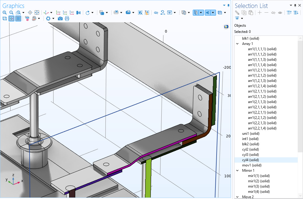
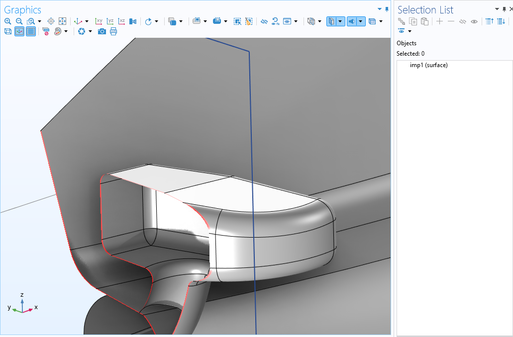 Examples of solid and surface objects, respectively. Clip planes are used to show the cross sections of the objects. Top: The solid objects of a busbar assembly contain domains (colorized here for visibility). Bottom: The side-view mirror of a sports car is modeled using theShellinterface and is therefore imported as a surface object, containing a closed void region.
Whenever we are talking about a geometric object in the software, we are referring to the collection of geometric entities that make up that object. When using theGeometrynode, also called thegeometry sequence, all geometry primitives and operations output geometric objects. When working outside of the geometry sequence, we are referring to geometric entities.
A geometry sequence in COMSOL Multiphysics®can contain one or several objects and a more complex geometry will consist of many objects. Before defining materials, physics, or mesh settings, the geometry is finalized using theForm UnionorForm Assemblynode. When building theForm UnionorForm Assemblyoperation, the geometry sequence and however many objects it comprises are automatically united into a single object with several domains. Thus, when setting up the materials, physics, and mesh in COMSOL Multiphysics®, we are always working with one object, even if the geometry consists of several entities that are not connected.
 A model of a viscoelastic damper shown in the Graphics window with the corresponding Extrude settings visible as well as the Selection List window with five objects listed.
A geometry comprised of five objects, which form a viscoelastic damper. AnExtrude operation is used to extrude the work plane sketches into solid objects. Lastly, the objects are mirroed with respect to the centerplate. The geometry has not yet been finalized. There are currently eight objects in the geometry, as evident in theSelection List window.
 A model of a viscoelastic damper shown in the Graphics window with the Form Union/Form Assembly settings visible as well as the Selection List window with one object listed.
 A model of a viscoelastic damper shown in the Graphics window with the Form Union/Assembly settings visible as well as the Selection List window with one object listed.
The viscoelastic damper geometry after being finalized through theForm Union node. Top: The five objects have been united into a single object (fin), as evident in theSelection List window. Bottom: The damper is now one object comprised of eight domains, as listed in theSelection List.
To sum up:
- In the geometry sequence, you are working with geometric objects and to some extent refer to geometric entities
- When the geometry is finalized, you assign material properties, mesh settings, and physics definitions on the geometric entities only
Geometric Entities
When assigning material properties, mesh settings, and physics definitions, the terminology used in COMSOL Multiphysics®for geometric entities (domains, boundaries, edges, and points) varies depending on the spatial dimension of your model component. A domain, for example, is always the geometric entity of the highest dimension for a model component. Thus, for a 3D geometry a volume is a domain. For a 2D geometry, an area is a domain, whereas a length is a domain for a 1D geometry. You can see how the terminology changes in this way in the image below.
 An infographic that is split into five columns, showing how the object, domain, boundary, edge, and point change depending on it being 3D, 2D, or 1D, using a piezoelectric shear-actuated beam as an example.
Infographic outlining the naming convention of geometric entities and how they change depending on the spatial dimension.
Notice that an edge only exists as a geometric entity for 3D models and how the naming convention for what boundaries represent also changes. Following domains, boundaries are always the geometric entities of the next-highest dimension. Thus, for a 3D geometry a surface, or face, is a boundary; for a 2D geometry a curve is a boundary; and for a 1D geometry a vertex is a boundary.
| Entity Dimension | Name in 3D | Name in 2D | Name in 1D | Name in 0D |
|---|---|---|---|---|
| 3D | domain | n/a | n/a | n/a |
| 2D | boundary | domain | n/a | n/a |
| 1D | edge | boundary | domain | n/a |
| 0D | point | point | boundary | domain |
Often while using the software, you will need to specify what is known as theGeometric entity levelwhen selecting parts of the model geometry. This refers to the type of geometric entity (object, domain, boundary, edge, or point), orlevel, from which you are making a geometry selection. For example, setting theGeometric Entity Levelselection toBoundaryfor any node in a 2D model enables you to select any number of edges.
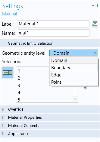
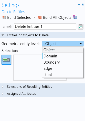
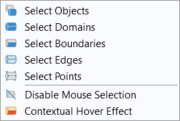
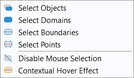
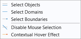
You can also see what can be selected at each geometric entity level option by using the Graphicswindow toolbar buttons for selecting geometry. The icons included in the drop-down menu for the geometric entity level also reflect the change in the names and entities for geometry according to spatial dimension. The dimension of each geometric entity is indicated by the icon to the left of each option.
| 3D | 2D | 1D |
|---|---|---|
 |
 |
 |
To see a demonstration of how the COMSOL naming convention with respect to geometry works and changes in the software, watch the tutorial video below.
Tutorial: Geometry Concepts and Nomenclature in COMSOL Multiphysics®
Further Learning
- COMSOL Documentation:COMSOL Reference Manual>About Geometric Entitieschapter
- Identifying and Selecting Geometric Entities by Index Number
- Selecting Geometry
- The usage of Form Union and Form Assembly
请提交与此页面相关的反馈,或点击此处联系技术支持。
