Defining Multiphysics Models Automatically with Multiphysics Interfaces
In COMSOL Multiphysics®, when defining the physics settings for a multiphysics model, you can completely streamline the process by utilizing the predefined multiphysics interfaces. This yields an almost fully automatic approach, whereas themanual approach with predefined couplingsandmanual approach with user-defined couplingsrequire manual tuning to implement. We will explain what this automatic approach is, detail the advantages of using it, and go over how to employ this functionality in a multiphysics model.
When to Use the Automatic Approach
The automatic approach greatly simplifies the modeling process by adding all the involved physics interfaces and multiphysics couplings using multiphysics interfaces. The multiphysics interfaces are automatically preconfigured for the specific combination of multiple physics phenomena being modeled. They are available for several disciplines of science and engineering, including electromagnetics, structural mechanics, acoustics, fluid flow, heat transfer, and chemical engineering.
The multiphysics interfaces formulate mathematical models as coupled systems of partial differential equations, which describe the coupled physics phenomena. In addition, the multiphysics interfaces also determine how this system of equations is discretized to form the corresponding numerical model equations, for example, using a finite element method, and how these equations are solved. This means that the multiphysics interfaces automatically include theoptimal element discretization settingsand solver settings for the specific system of equations. In this way, the automatic approach enables you to more quickly get to and focus on defining the multiphysics model, without having to get bogged down with formulating the mathematical couplings or with the numerical technicalities that may be involved if you have to do the work from scratch.
For a complete list of the multiphysics interfaces available to you for any COMSOL products you hold a license for, you can view theSpecification Chart. There are a number of ways you can browse the chart, as noted in aprevious blog post. Simply select the application area your module(s) fall under or the modules themselves (or both) and scroll down to thePredefined Multiphysics Interfacessection to see the list of built-in multiphysics interfaces. You can also see a list and short description of the physics interfaces and multiphysics interfaces that come with any modules you have a license for in the module's introduction documentation, under the physics interfaces chapter. Further details are available in the module's user's guide documentation under the physics interface guide chapter. For example, if you have licensing for the AC/DC Module, you can find a list of the physics interfaces in theIntroduction to the AC/DC Moduledocumentation underThe AC/DC Module Physics Interfaceschapter. You could find further details in theAC/DC Module User's Guideunder theAC/DC Module Physics Interface Guide.
 A screenshot of the Specification Chart for the COMSOL® software, with options selected for heat transfer and predefined multiphysics interfaces.
The Specification Chart with the Heat Transfer application area selected and the Predefined Multiphysics Interfaces section displayed.
Now that we have discussed the advantages of this approach, we will outline the steps and show the use of it with an example in subsequent sections.
Procedure to Implement the Approach
Implementing the automatic approach when defining a multiphysics model requires only a few steps, since the model setup is expedited with the respective physics interfaces and the multiphysics couplings already included. As such, a general outline of the procedure for using the automatic approach is as follows:
- Add the multiphysics interface
- Define the physics settings (boundary conditions, initial conditions, constraints, loads, material properties, etc.) for each of the constituent physics interfaces
Below, we demonstrate use of the approach with a tutorial model serving as our multiphysics example.
Walkthrough Example: Modeling Resistive Heating and Thermal Expansion
Let’s use the thermal-electrical-mechanical (“tem”) version of thethermal microactuator tutorial modelfound in the Application Libraries to demonstrate the automatic approach for adding the physics interfaces for a multiphysics model.
Note: For the sake of brevity, assume that all steps in the modeling workflow, apart from defining the physics settings, are complete. Thus, the geometry, materials, mesh, and study are already set up. Additionally, we will narrow our focus to defining the multiphysics aspects of the model and not go into detail regarding how to add and define specific boundary conditions for the constituent physics interfaces.
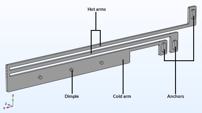
First, we define the physics settings for Joule heating and thermal expansion. A voltage is applied between the two anchors connected to the hot arms, as pictured in the figure below. The conducted current is resisted as it flows through the actuator's hot arms, resulting in electric heating, which raises the temperature of the hot arms and causes them to expand through thermal expansion. The cold arm does not expand to the same extent and this causes the actuator to move in the negativey-direction in the figure. The base of all of the anchors are fixed, but the dimples enable the arms to move in the xy-plane.

The thermal microactuator geometry with the parts labeled. The device is made of polycrystalline silicon.
To study the electrical-thermal-structural interaction that occurs, we can use the predefinedJoule Heating and Thermal Expansioninterface. To include this multiphysics interface in the simulation:
- Open theAdd Physicswindow
- Expand theStructural Mechanics>Thermal-Structure Interactionbranch
- Select and add theJoule Heating and Thermal Expansioninterface to the model component
Upon adding Joule heating and thermal expansion to the model, notice that several physics interface nodes have also been added to the model tree. These include theElectric Currentsinterface;Heat Transfer in Solidsinterface;Solid Mechanicsinterface; and aMultiphysicsnode containing the couplings for electromagnetic heating and thermal expansion.
 A screenshot of the Model Builder, with the thermal microactuator model open and the Electromagnetic Heating interface expanded.
A screenshot of the physics and multiphysics nodes (each with with the corresponding settings) that are automatically added to the model tree when using the automatic approach.
TheElectromagnetic Heatingmultiphysics coupling uses the electric current and the electric conductivity to add the resistive heating as a heat source in the heat transfer equations. Note also that temperature may influence the electrical and thermal conductivities. TheThermal Expansionmultiphysics coupling uses the temperature field and the coefficient of thermal expansion in the formulation of the thermal strain vector in the structural mechanics model, yielding the expansion and the stresses and strains caused by this expansion when the model is computed.

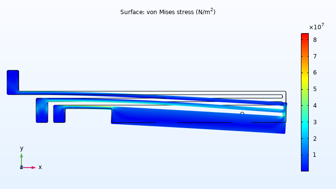
An xy-plane view of the results for stress and deformation of the thermal microactuator.
As you can see, the automatic approach makes a complex problem quite easy to define and solve. You don’t have to worry about recalling if you’ve included the correct multiphysics nodes, applied the appropriate settings from one physics interface to another, or defined the proper solver settings, since it is all automated.
From this point forward, we can focus on defining the physics settings for each individual physics interface, such as adding any necessary boundary conditions or constraints and editing the settings.
To see how to build the complete model using this approach, watch the tutorial video below for a full demonstration.
Tutorial: Defining a Multiphysics Model Using the Automatic Approach
Modeling Exercises
Demonstrate the knowledge you have gained from this article by putting it into practice with the follow-up modeling exercises listed below. The directions provided for each modeling exercise contain all the information necessary in order to complete it, but are intentionally generalized to encourage self-guided problem solving. You can check your implementation with the solution model files provided here manually or use theComparison toolto exactly identify the differences.
- Follow thedirectionsprovided to build the busbar tutorial model using the automatic approach. The geometry file is available to download:busbar.mphbin.
- Follow thedirectionsprovided to build the free convection tutorial model using the automatic approach. The geometry file is available to download:free_convection.mphbin.
请提交与此页面相关的反馈,或点击此处联系技术支持。
